User manual - DRR245 11
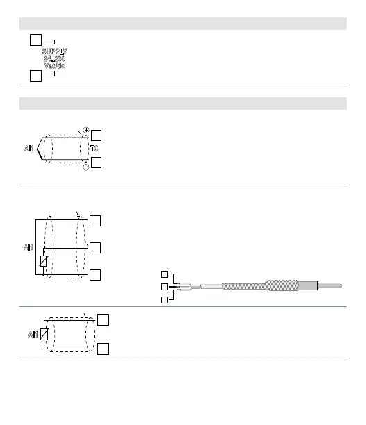
6.1.a Power supply
SUPPLY
24..230
Vac/dc
Switching supply with extended range
24..230 Vac/dc ±15% 50/60Hz – 5,5VA
(galvanic isolated)
6.1.b AN1 analogue imput
13
14
AI1
TC
Shield/Schermo
For thermocouples K, S, R, J.
• Comply with polarity.
• For possible extensions, use a compensated wire
and terminals suitable for the thermocouples used
(compensated).
• When shielded cable is used, it should be grounded
at one side only.
13
14
AI1
PT/NI100
Shield/Schermo
Rosso
Red
Bianco
White
Rosso
For thermoresistances PT100, NI100.
• For the three-wire connection use wires with the
same section.
• For the two-wire connection short-circuit terminals 1
and 3.
• When shielded cable is used, it should be grounded
at one side only.
• Select internal jumper JP3 as in the figure.
15
14
13
RED/ROSSO
RED/ROSSO
WHITE/BIANCO
14
AI1
For thermoresistances NTC, PTC, PT500, PT1000 e
potentiometers.
When shielded cable is used, it should be grounded at
one side only to avoid ground loop currents.