14 - DRR245 - User manual
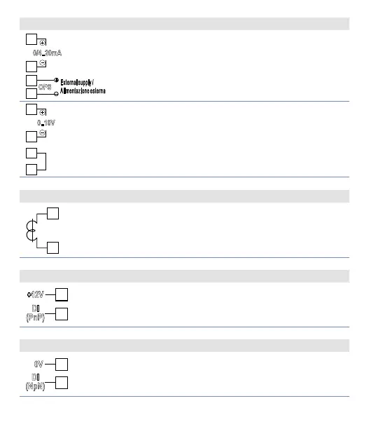
6.1.g mA / Volt output
11
8
0/4..20mA
OPS
External supply /
Alimentazione esterna
Pins 11-12: linear output in mA configurable using
parameters as command (Parameter
c.out
) or
retransmission of process or setpoint (Parameter
re t r.
).
Pins 7-8: optional external power supply for current
loop (max 24Vdc).
11
10
0..10V
Linear output in Volt configurable using parameters
as command (Parameter
c.out
) or retransmission of
process or setpoint (Parameter
re t r.
).
Short-circuit pins 9 and 10 as in the figure to use
linear output in Volt.
6.1.h Current transformer input
18
19
TA
• Input 50mA for amperometric transformer
• Sampling time 80ms
• Configurable by parameters
6.1.i Digital Input 1
+12V
DI
Use of digital input without T.A. input
Digital input according to parameter
d G t.i .
Short-circuit pins 16 and 17 as in the figure to
activate the digital input.
6.1.j Digital Input 2
15
DI
(NpN)
0V
Combined use of digital input and T.A. input
Digital input according to parameter
d G t.i .
This combined use is possible only with sensors TC,
0..10V, 0/4..20mA, 0..40mV.