12 - DRR245 - User manual
13
14
16
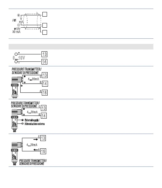
AI1
V
mA
+12V
30 mA
Shield/Schermo
For linear signals V / mA.
• Comply with polarity.
• When shielded cable is used, it should be grounded
at one side only.
6.1.c Example of connection for linear input Volt and mA
14
0...10V
For signals 0..10 V.
Comply with polarity.
SENSORE DI PRESSIONE
P :0...100mbar
Pmax :3bar
T :0..70°C
OUT : 4...20mA
16
14
13
B
C
A
4...20mA
For signals 0/4..20 mA with three-wire sensor.
Comply with polarity:
A= Sensor output
B= Sensor ground
C= Sensor power supply (12Vdc / 30mA)
External supply /
Alimentazione esterna
P :0...100mbar
Pmax :3bar
T :0..70°C
OUT : 4...20mA
IN :9...33V DC
PRESSURE TRANSMITTER /
SENSORE DI PRESSIONE
14
13
C
B
4...20mA
For signals 0/4..20 mA with external power of sensor.
Comply with polarity:
A= Sensor output
B= Sensor ground
P :0...100mbar
Pmax :3bar
T :0..70°C
OUT : 4...20mA
IN :9...33V DC
16
A
PRESSURE TRANSMITTER /
4...20mA
For signals 0/4..20 mA with two-wire sensor.
Comply with polarity:
A= Sensor output
C= Sensor power supply (12Vdc / 30mA)