User manual - DRR245 15
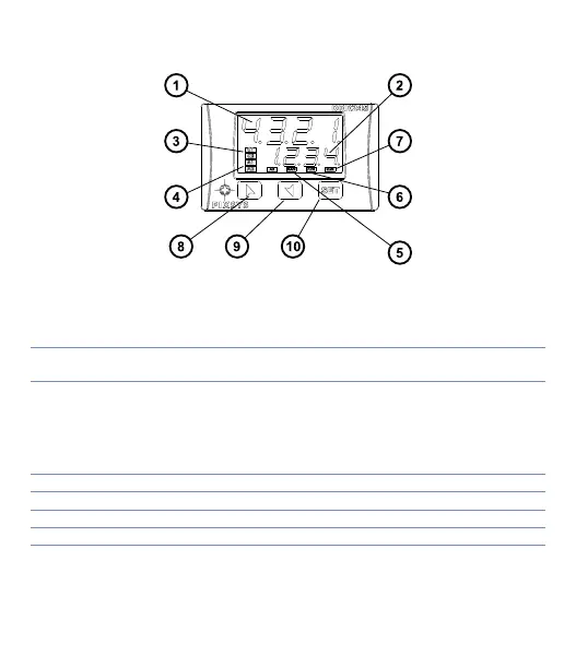
7 Display and Key Functions
7.1 Numeric Indicators (Display)
1
1234
Normally displays the process. During the configuration
phase, it displays the parameter being inserted.
2
1234
Normally displays the setpoint. During the configuration
phase, it displays the parameter value being inserted.
7. 2 Meaning of Status Lights (Led)
3 C1 C2
ON when the output command is on.
C1 with relay/SSR/mA/Volt command or C1 (open) and C2
(close) for a motorised valve command.
4 A1 A2 A3 ON when the corresponding alarm is on.
5 MAN ON when the “Manual” function is on.
6 TUN ON when the controller is running an “Autotune” cycle.
7 REM ON when the controller communicates via serial port.