User’s Manual of IVS-H125 Series
12
Chapter 2.
Hardware Interface
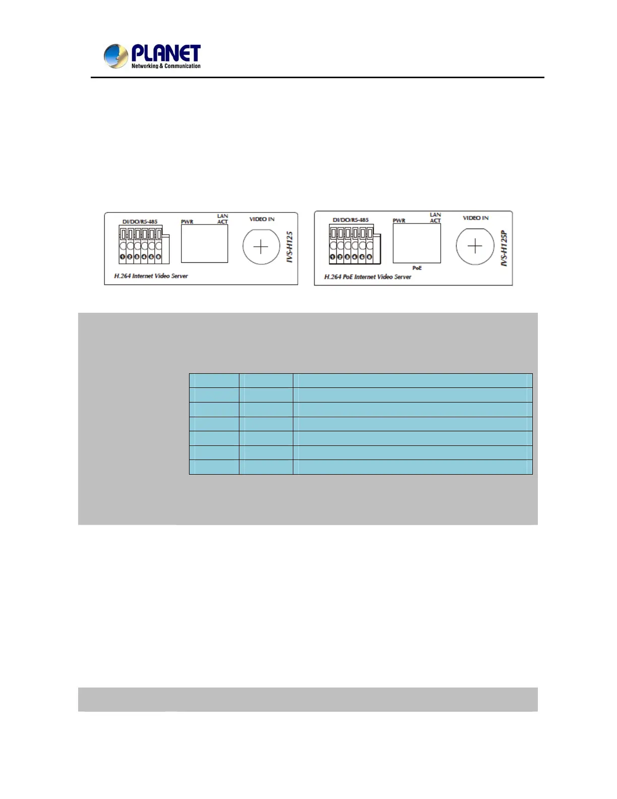
2.1. Left-hand side Panel
DI/DO/RS-485
This IVS-H125 and IVS-H125P provide a general I/O terminal block with one
digital input and one output for device control. It has 6 Pins that from left to right
that are 12V DC power supply (50mA maximum), Alarm Input, GND, Alarm
Output, D+ terminal of RS-485 and D- terminal of RS-485.
Name Number Function
12VDC 1 DC 12V (50mA maximum)
DI 2 Digital signal input
GND 3 GND
DO 4 Digital signal output
485+ 5 RS485 data +
485- 6 RS485 data -
NOTE: The RS-485 of IVS-H125 is master that can control external scanner or
PTZ camera.
RJ-45
Connects to 10Base-T Ethernet or 100Base-TX Fast Ethernet cabling. This
Ethernet port built N-Way protocol can detect or negotiate the transmission
speed of the network automatically. Please use Category 5 cable to connect the
Network Camera to a 100Mbps Fast Ethernet network switch or hub.
In the LAN socket, there are two LED embedded:
LAN LED (green color)
This LED will be flashing while network accessing via Ethernet.
Power LED (orange color)
This LED is used to indicate whether DC power is on or not. In addition, this LED
will be flashing while network accessing via Ethernet.
Video In You can install an analog camera and connect it to video-in jack.

 Loading...