POCLAIN HYDRAULICS
76 DOC-REPAIR-MS25-MS125-FR-EN 800378131M
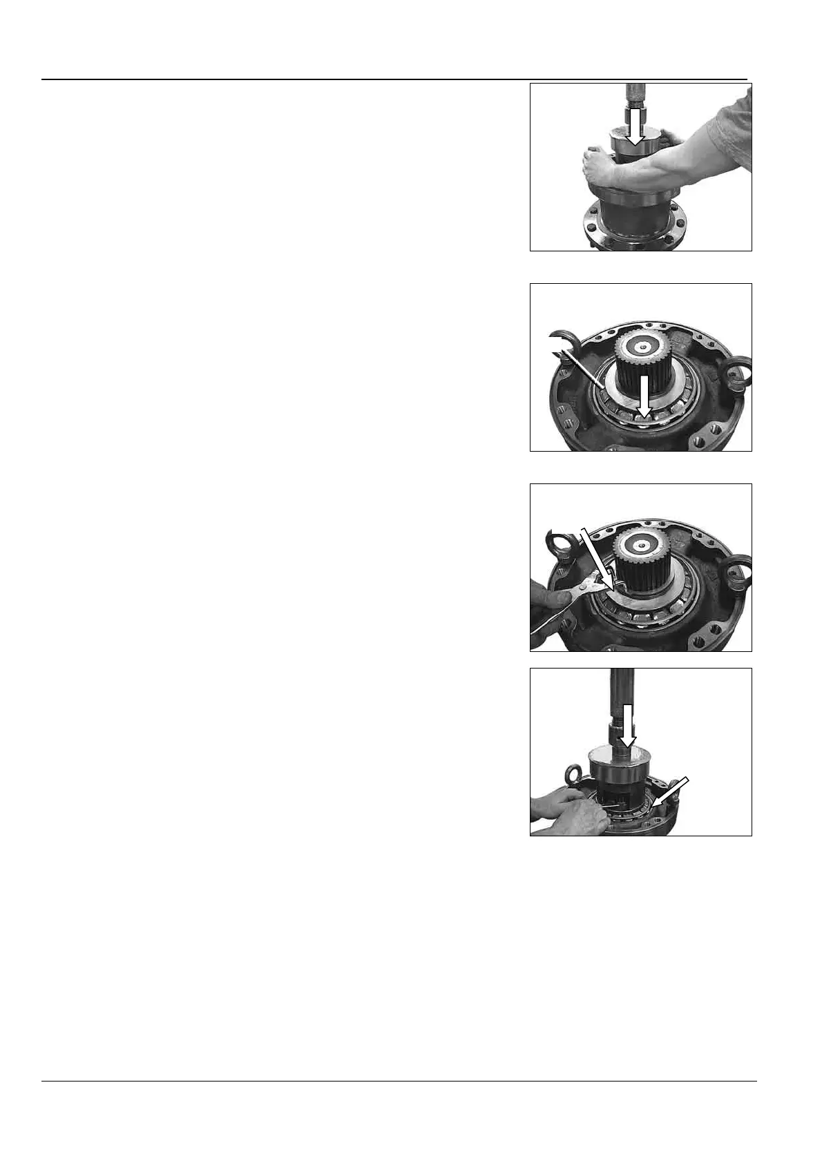
• Relâcher l’effort F (voir tableau
page 107) jusqu'à obtenir
20 000 N.[4500 lbf] et s’assurer de
la mise en place des roulements
par la rotation du palier (5 tours mini
à droite et à gauche).
• Appliquer à nouveau l’effort F
(voir tableau page 107) sur le
roulement (074) à l’aide d’un
mandrin.
• Release the F force (see table
page 107) up to 20 000 N [4500 Ibf]
and check the bearings position by
turning the bearing support
(minimum 5 rev. to the right and
left).
• Using a mandrel press again
with F force (see table page 107) on
the bearing (074).
• Relâcher l'effort F, et monter la
bague d’appui (076).
• Release the F force, and install
the thrust ring (076).
• Monter l’anneau d’arrêt (077)
en utilisant une pince à anneaux
d’arrêt extérieurs.
• Remove the snap ring (077)
using external snap ring pliers.
• Appliquer l’effort F (voir tableau
page 107) sur le roulement (074),
puis mesurer le jeu entre la bague
d’appui (076) et l’anneau d’arrêt
(077).
• Déterminer le calage (075) afin
d'obtenir le couple de rotation (C)
correspondant (voir tableau page
107), (valeur approximative du
calage = mesure).
• Apply the F force (see table
page 107) on the bearing (074),
then measure the clearance
between the thrust ring (076) and
the snap ring (077).
• Determine the shimming (075)
in order to obtain the rotational
torque (C) (see table page 107)
(Approximate shimming value =
measure).
076
077