POCLAIN HYDRAULICS
800378131M REPAR MS25-125 F/GB 47
• Relâcher l’effort F (voir tableau
page 86
) jusqu'à obtenir
20 000 N.[4500 lbf] et s’assurer de
la mise en place des roulements par
la rotation du palier (5 tours mini à
droite et à gauche)
Appliquer à nouveau l’effort F (voir
tableau page 86
) sur le roulement
(074) à l’aide d’un mandrin.
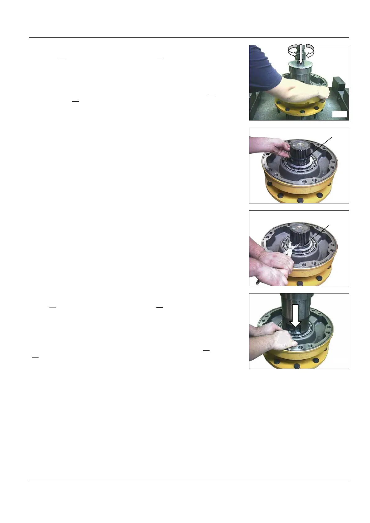
• Release the F force (see table
page 86
) up to 20 000 N [4500 Ibf]
and check the bearings position by
turning the bearing support (mini-
mum 5 rev. to the right and left)
Using a mandrel press again with F
force (see table page 86
)onthe
bearing (074).
• Relâcher l'effort F, et monter la
bague d’appui (076).
• Release the F force, and install
the thrust ring (076).
• Monter l’anneau d’arrêt (077) en
utilisant une pince à anneaux d’arrêt
extérieurs.
• Remove the snap ring (077) us-
ing external snap ring pliers.
• Appliquer l’effort F (voir tableau
page 86
) sur le roulement (074),
puis mesurer le jeu entre la bague
d’appui (076) et l’anneau d’arrêt
(077).
• Déterminer le calage (075) afin
d'obtenir le couple de rotation (C)
correspondant (voir tableau page
86
),(valeur approximative du calage
= mesure + S).
• Apply the F force (see table
page 86
) on the bearing (074), then
measure the clearance between the
thrust ring (076) and the snap ring
(077).
Determine the shimming (075) in
order to obtain the rotational torque
(C) (see table page 86
) (Approxi-
mate shimming value = measure +
S).
8322
8323
076
8324
8325
077