10.14
ELECTRICAL
ALL WHEEL DRIVE COIL
Operation Overview
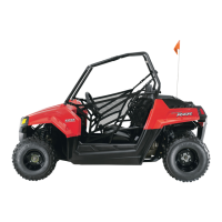
• When the AWD switch is “ON”, 12 VDC power is
present at the hub coil.
• If the criteria is met, the instrument cluster provides a
ground path at pin #16. When this occurs the AWD
icon should display in the instrument cluster.
• The AWD system must be grounded to operate.
Diagnosing System Failures
• Verify the AWD switch is functional and that a
minimum of 11 volts is present at the hub coil.
• Verify the AWD hub coil is functional. Test the AWD
hub coil using an ohm meter. See specifications below:
• Verify the wiring harness, wiring, connectors,
connector pins and grounds are undamaged, clean and
connect properly.
• Verify continuity of wire connections with a known
good volt/ohm meter.
IMPORTANT: Verify all wires and wiring connections
have been tested properly with a known good volt/
ohm meter before suspecting a component failure.
80% of all electrical issues are caused by bad/failed
connections and grounds.
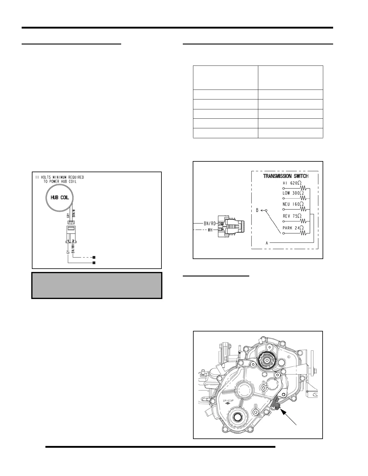
GEAR POSITION INDICATOR SWITCH
Switch Resistance Value Table
NOTE: See “Instrument Cluster Troubleshooting”
for additional switch circuit information.
SPEED SENSOR
Location / Testing
The speed sensor is located in the transmission transfer case
cover and can be accessed through the rear LH wheel well area.
To test the Speed Sensor, refer to “TEST 3” under
INSTRUMENT CLUSTER TROUBLESHOOTING TESTS.
AWD Hub Coil Resistance:
24 Ω ± 5%
7HVW5HVLVWDQFH
5HDGLQJVVKRXOGEH
*<WR%1:+a2KPV
*<WR*URXQG1R&RQQHFWLRQ
Gear Position
Resistance Value
when measured at
terminals A and B
HIGH 620 Ω
LOW 300 Ω
NEU 160 Ω
REV 75 Ω
PARK 24 Ω
Speed Sensor

 Loading...