Page 8
ENGLISH
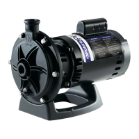
Polaris® PB4SQ™ Booster Pump | Installation and Operation Manual
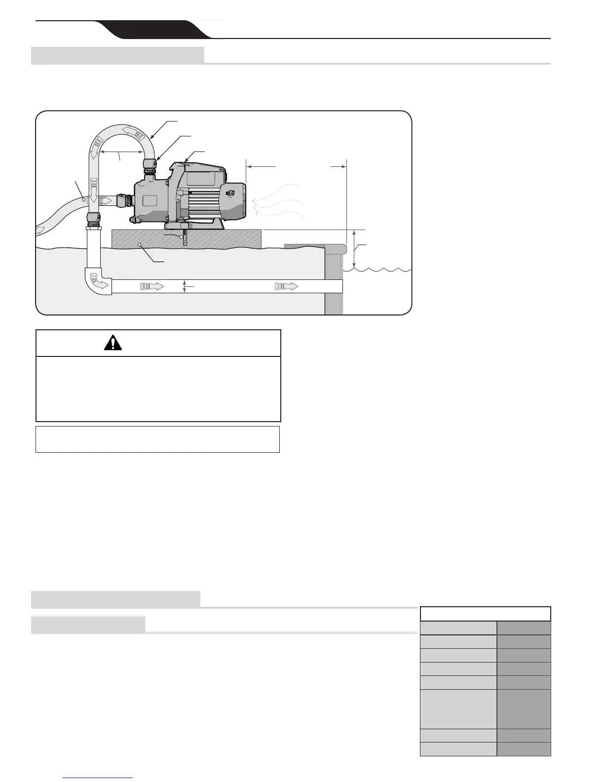
4.2 Location Requirements
• Pump must receive constant ow from the lter
pump. The PB4SQ is not a self priming pump.
See Figure 2.
PB4SQ Booster Pump
Quick Connect Assembly
Reinforced Hose
5' (1.5 m) min.
From Inner Pool Wall
10' (3 m) min. in Canada
Provide
adequate
clearance for
intake air.
Minimum 3” is
recommended
• A dedicated return line is required.
• DO NOT USE flexible tubing of any kind for an underground return line.
• Plumb upstream of all air inducing equipment.
• Install on a solid level surface that will not vibrate.
• A concrete slab/equipment pad is recommended.
• To reduce noise bolt the pump to the concret equipment pad.
• Ensure the equipment pad has sufficient drainage
1 1/2" (40 mm) PVC min.
1' (30.5 cm) min.
Above Pool
Water Level
Must maintain
constant flow
from filter pump
Min Ø
12” (304.8mm)
To Cleaner
Expansion Anchor
Figure 3. Location Requirements
Some Safety Vacuum Release System (SVRS)
devices are not compatible with the installation of
check valves. If the pool is equipped with an SVRS
device, be sure to conrm that it will continue to
safely operate when check valves are installed.
WARNING
NOTE: For installations in Canada the distance from the inner
pool edge must be 10' (3 m).
• The pump along with all other circulation
equipment must be installed at least 5' (1.5 m) from
the inner pool edge. See Figure 3.
• The pump must be placed on a solid foundation that
will not vibrate. See Figure 3.
• Install the pump as close to the pool as possible and
in a position that will minimize bends in the piping.
• Secure the pump by bolting it to the equipment pad.
This will also have the added benet of helping to
reduce vibration noise. See Figure 3.
• The booster pump inlet connection line should be at
least 3/4” pipe.
• To help prevent difculty in priming, install the
inlet line without high points
or air locks.
• The Quick Connect ttings
are designed to work with the
Polaris reinforced hose (part
#P19). See Figure 8
• Return line should be
rigid PVC at 1 1/2" (40 mm)
Minimum. See Figure 3
• Plumb return line upstream
of any air inducing equipment.
• Install the booster pump
within 1' (30.5 cm) of the pool
water surface. See Figure 3
• The pump should not be
elevated more than a few feet
above the water level of the pool.
• If the pump is installed below the water level,
check valves must be installed on both the inlet and
return lines to prevent back ow during service or
maintenance of the pump.
• The equipment pad must have adequate drainage to
prevent water intrusion to the pump.
• The pump needs to be protected from extreme
weather exposure.
• Proper ventilation is required in order to avoid
excess heat buildup at the pump motor.
• Ensure that sufcient service and maintenance
clearances are provided.
• The area around the pump should be clear and free
of debris.
• Sufcient space must be left above the pump to
allow access to the electrical connections.
• If the equipment is under cover, provide adequate
lighting.
• Do Not Install under the skirt or within the outer
enclosure of a spa.
4.3 Electrical Connections
4.3.1 Supply Voltage
The pump can be wired for supply voltage of either
230VAC or 115VAC. The pump comes factory wired
for 230VAC installation. See section 4.3.3 for details
on wiring the motor for 115VAC supply. Correct
supply voltage is necessary for proper performance and
sustained motor life.
It is the responsibility of the electrical installer to
provide proper operating voltage, based on the pump
motor rating information found here or on the pump
rating plate, ensuring
proper circuit sizes
and wire sizes for this
specic application.
The National Electrical
Code
®
(NEC
®
, NFPA-
70
®
) requires all
pool pump circuits
be protected with a
MOTOR RATING
MODEL PB4SQ
OUTPUT WATTS 725
HP 0.97
SERVICE FACTOR 1.0
RPM 3450
VOLTS AC
230/115VAC,
1 PHASE,
60 HZ
AMPS 4.5/9.2
DUTY CONT
 Loading...