Page 9
ENGLISH
Polaris
®
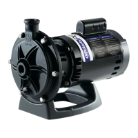
PB4SQ™ Booster Pump
|
Installation and Operation Manual
Ground Fault Circuit-Interrupter (GFCI). Therefore,
it is also the responsibility of the electrical installer
to ensure that the pump circuit is in compliance
with this and all other applicable requirements of
the National Electrical Code
®
(NEC
®
) and any other
applicable installation codes.
Failure to provide data plate voltage (within 10%)
during operation will cause the motor to overheat
and void the warranty.
CAUTION
4.3.2 Bonding and Grounding
The motor frame must be grounded to a reliable
grounding point using a solid copper conductor, No.
8 AWG (8.4mm
2
) or larger. In Canada, No. 6 AWG
(13.3mm
2
) or larger must be used. Do not ground to a
gas supply line.
The motor must be bonded to all metal parts of the
swimming pool, spa, or hot tub structure and to all
electrical equipment, metal conduit, and metal piping
within ve (5) feet (1,5 meter) of the inside walls of the
swimming pool, spa, or hot tub. Bond the motor using
the provided external lug.
To avoid the risk of property damage, severe
personal injury, and/or death, always disconnect the
power source before working on a motor or its
connected load.
WARNING
To avoid the risk of property damage, severe personal
injury, and/or death, make sure that the control switch
or time clock is installed in an accessible location so
that in the event of an equipment failure or a loose
plumbing tting the equipment can be turned off. This
location must not be in the same area as the pool
pump, lter, and other equipment.
WARNING
The pump must be permanently connected to a
dedicated electrical circuit. No other equipment,
lights, appliances or outlets may be connected to
the pump circuit, with the exception of devices that
may be required to operate simultaneously with the
pump, such as a chlorinating device or heater.
CAUTION
4.3.3 Electrical Wiring
MAXIMUM WIRE SIZE AND MAXIMUM OVERCURRENT PROTECTION*
Distance from Sub-Panel 0-50 feet (15 meters) 50-100 feet (15-30 meters) 100-200 feet (30-60 meters)
Pump
Model
Branch Fuse AMPs
Class: CC, G, H, J, K, RK, or T
Voltage Voltage Voltage
230 VAC 115 VAC 208-230 VAC 115 VAC 208-230 VAC 115 VAC 208-230 VAC 115 VAC
PB4SQ 15A 15A
14 AWG
(2.1mm
2
)
12 AWG
(3.3mm
2
)
12 AWG
(3.3mm
2
)
10 AWG
(5.3mm
2
)
10 AWG
(5.3mm
2
)
10 AWG
(5.3mm
2
)
*Assumes three (3) copper conductors in a buried conduit and 3% maximum voltage loss in branch circuit. All National Electrical Code
®
(NEC
®
) and
local codes must be followed. Table shows minimum wire size and branch fuse recommendations for a typical installation per NEC.
1. Turn off all electrical power at the breakers.
2. Ensure that the pump is installed and rmly attached to
a solid foundation. See Figure 3.
3. Use exible conduit to route supply power lines
to pump location.
4. Determine the best conduit port to use. There is one on
the side and one in the back of the capacitor housing.
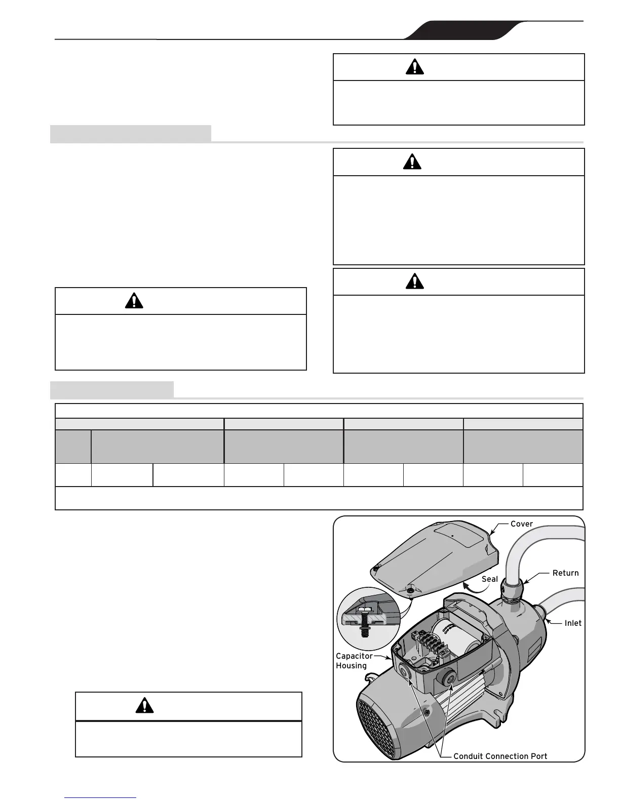
5. Loosen do not remove the 4 screws securing the
electrical housing cover to the pump body. See Figure 4.
6. Remove the electrical housing cover and seal assembly.
7. Inspect the cover and seal for any damage or improper
seating. Replace if necessary.
Conduit hubs suitable for wet locations that comply
with the requirements in the Standard for Conduit,
Tubing, and Cable Fittings, UL 514B, are to be used.
Figure 4. Removing Electrical Access Cover
Be careful not to overtighten any conduit tting.
Overtightening can cause the housing to crack.
CAUTION
 Loading...