3
9850043 R01 - 2017-2021 RANGER 500 / 570 Service Manual
© Copyright Polaris Inc.
3.113
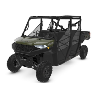
6. Install the upper cam chain guide and the eight bolts
that retain the camshaft carrier.
7. Torque the camshaft carrier bolts in sequence to
specification.
TORQUE
Camshaft Carrier Bolts:
7 ft-lbs (10 N·m)
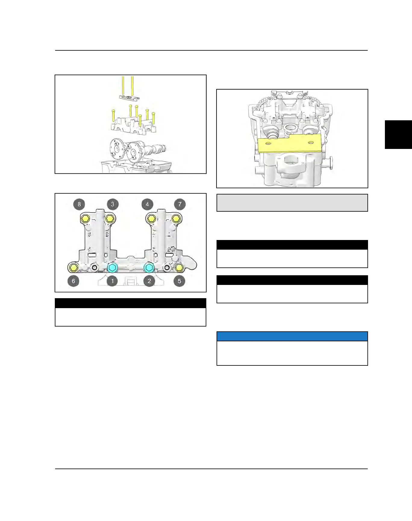
8. Install the Cylinder Holding and Camshaft Timing
Plate into the end of camshafts as shown below. The
thermostat housing must be removed to install the
timing plate PU-50563.
Cylinder Holding / Camshaft Timing Plate:
PU-50563
9. Measure the valve clearance of each valve using a
thickness (feeler) gauge. Record the measurement if
clearance is out of specification.
MEASUREMENT
Intake Valve Clearance (cold):
.006 ± .002″ (0.150 ± .050 mm)
MEASUREMENT
Exhaust Valve Clearance (cold):
.008 ± .002″ (0.200 ± .050 mm)
10. If any of the valve clearance measurements are out
of specification, remove the camshaft carrier and
camshafts and proceed with this procedure.
NOTICE
If all valve clearance measurements are within
specification, remove the camshaft carriers and
proceed to “Camshaft Installation / Timing”.
ENGINE / COOLING SYSTEM
 Loading...