3-30
P-Link Devices
NoteSection 6:
PSN-1000/PSN-1000(E) – Installing, Operating & Programming,
Conguration Characteristics
y
y
y
Maximum Wire Resistance Formula
load
(Total Annunciator Alarm Current) x (Wire Resistance) < 6 Volts
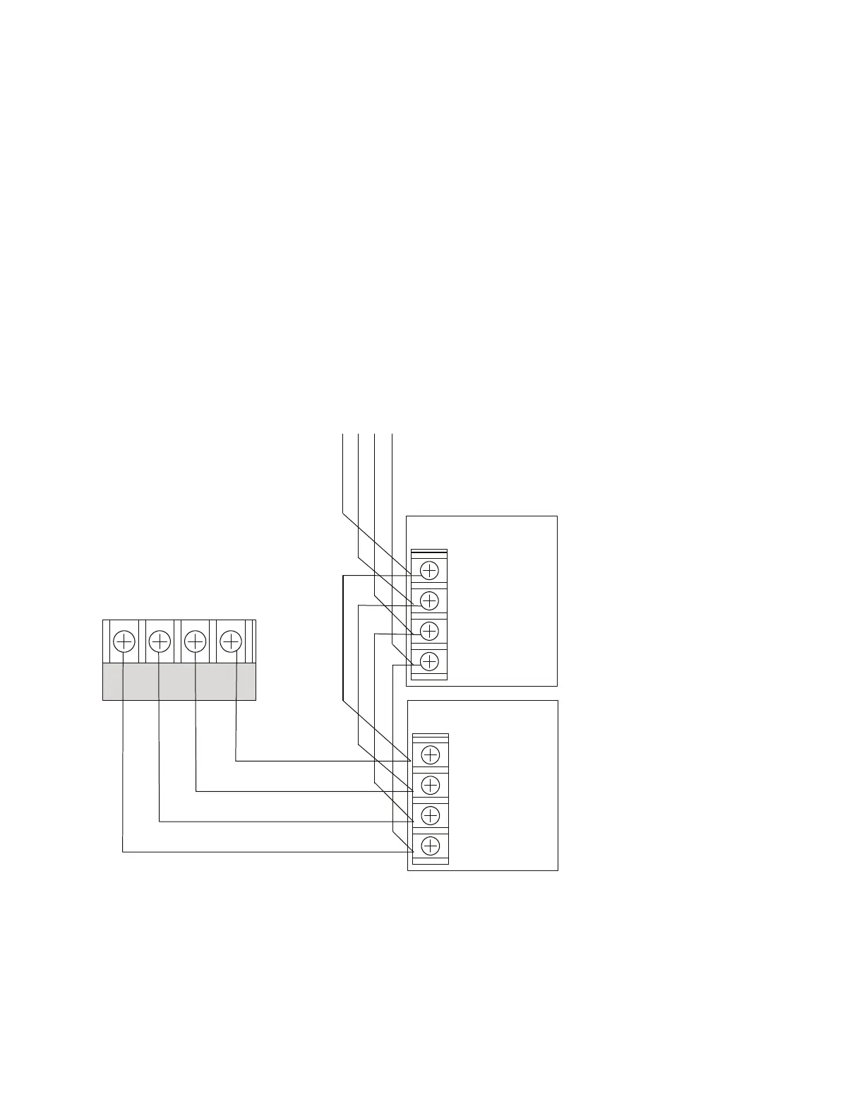
P-Link Class B Wiring ExampleFigure 29.
To the next device
- + A B
Expansion
Device
- + A B
P-LINK
- + A B
Panel
Connection
Expansion
Device
DWG #602-11A


 To Next Page