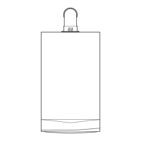
3.3 Dimensions and connections/clearances
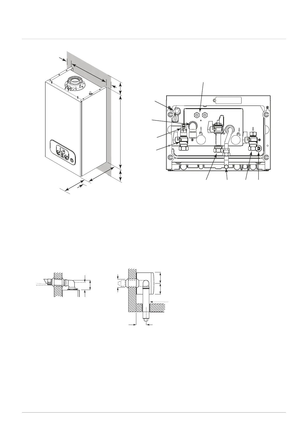
Fig.3 Dimensions and connections / clearances
1
2
3
4
5
6
7
PN-0000624
9
700
285
390
5
5
178
200
450
5
10
The clearances shown in the diagram are minimum requirements
to allow for case removal, spanner access and air movement.
These should be observed at all times and kept clear of obstructions.
1
Condensate trap sump
2
Condensate drain
3
Heating circuit water flow
4
Gas inlet
5
Pressure relief pipe
6
Heating circuit water return
7
Pump drain point
9
Cable entry points
10
Boiler drain point on flow isolation tap
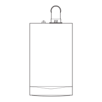
Fig.4 Flue position
=
=
160
106
>1.5°
Ø1
16 min
154
Ø100
PN-0000649
3 Technical specifications

 Loading...