Replace PCB
Check and correct if necessary
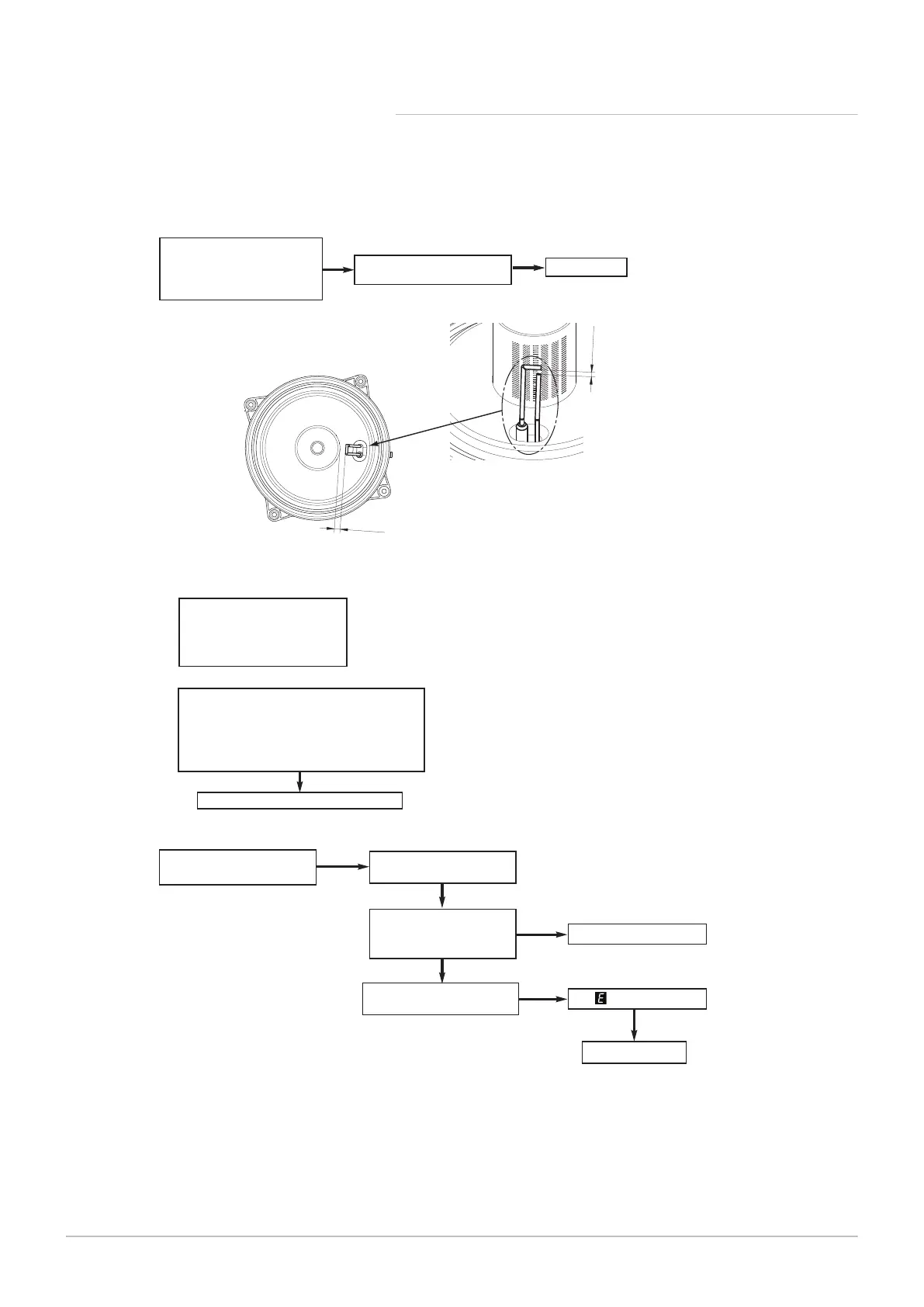
1. Ignition electrode and lead
2. Electrode connection
3. Spark gap and position
Check wiring - see Electrical
Wiring Diagram page 18
YES
NO
F
4
±
0.5
1
0
±
1
Check and correct if necessary
1. The set of the gas valve
(CO2 values - see instruction)
2. Flame sensing electrode and lead connections
3. Flame sensing electrode position
1.
2.
G
Replace flame sensing electrode or PCB
Replace PCB
YES
Replace safety thermostat
YES
YES
Safety thermostat operated
or faulty
Check for and correct any
system faults
H
Allow to cool. Continuity
across thermostat terminals
more than 1.5 ohm
NO
Check Flow & Return Sensors
- see section ‘D’
NO
Is 110 still flashing ?
YES
Check supply pressure at the
gas valve:-
Natural Gas - Minimum 17 mbar
PN-0000318

 Loading...