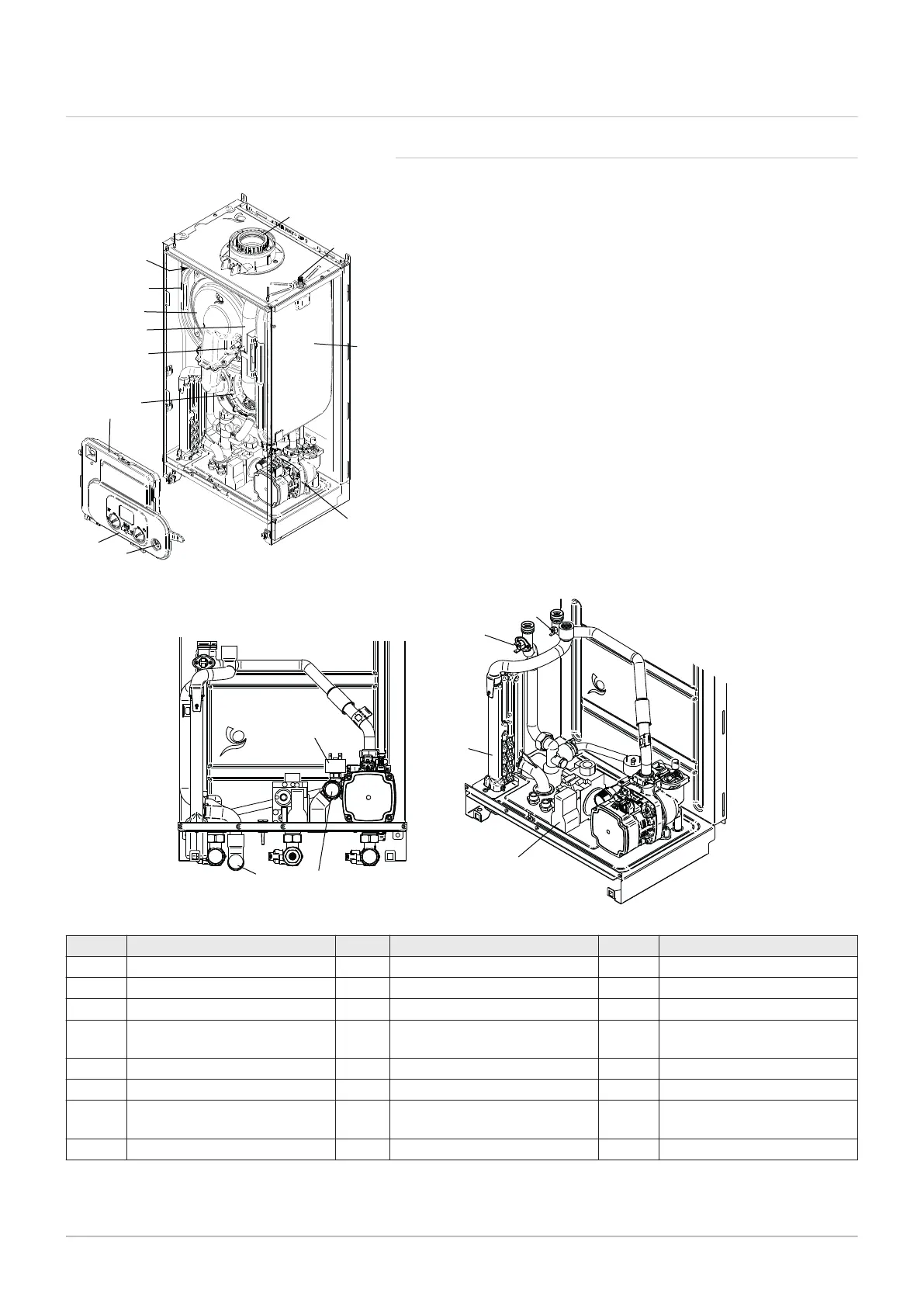
4.3 Main components
4.3.1 List of components
Fig.9 Hydraulic layout
Tab.15 Component descriptions
Key Description Key Description Key Description
1 Expansion vessel 9 Flue sensor 17 Flue adaptor
2 Expansion vessel valve 10 Spark ignition electrode 18 Heating flow sensor
3 Primary heat exchanger 11 Control box 19 Safety thermostat
4 DHW plate heat exchanger (not
on System Models)
12 Condensate trap 20 Water Pressure Switch
5 Pump with automatic air vent 13 Safety pressure relief valve 21 Condensate outlet
6 CH system pressure gauge 14 Gas valve 22 Silencer
7 Fan assembly 15 Diverter valve motor (not on
System Models)
23 Hall effect sensor (not on Sys
tem Models)
8 Burner / door assembly 16 Boiler controls
Fig.8 Component descriptions
PN-0000262
1
2
17
5
3
6
16
7
8
9
11
10
22
4 Description of the product

 Loading...