3.4 Electrical diagram
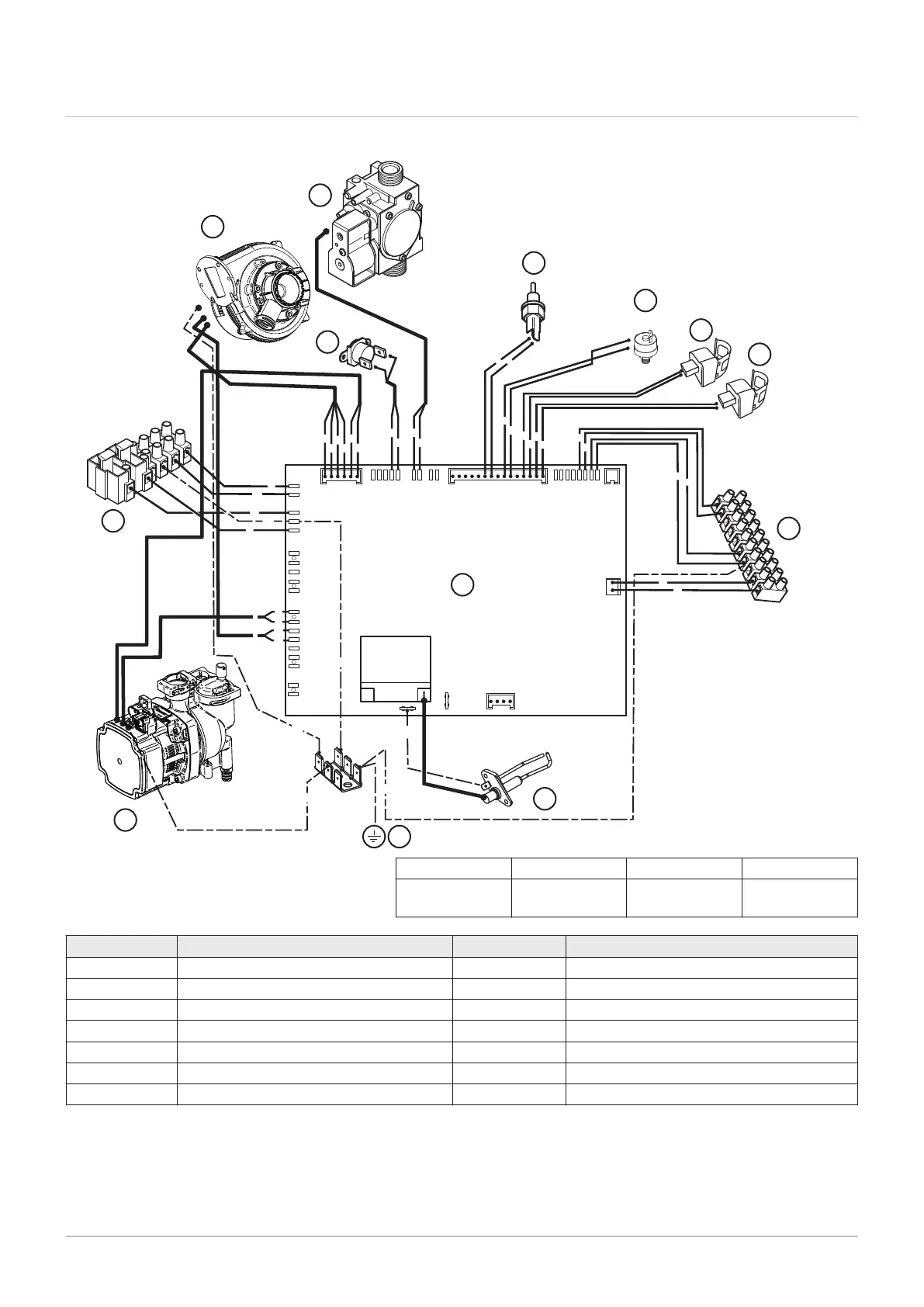
Fig.5 Electrical wiring diagram
X23 X37 X36
X22 X20 X24
X10
X11
X12
X13
X1
X2
X3
g g
g
r
r
g
b
g
b g
br
bk
b
b
r
r
br
b
g/y
g/y
g/y
g/y
g/y
br
X31
br
br
PN-0000342
A
C
D
E
F
H
I
K
L
N
M
b
br
b
b
O
P
L
N
E
M1
1
2
5
6
7
8
9
1
0
3
4
M2
b
bk
bk
bk
br
g
g
g/y
bk — black br — brown b — blue g — green
r — red w — while g/y — green/
yellow
Key Description Key Description
A Gas valve K Pump
C Flue sensor L Terminal strip
D Hydraulic pressure switch M Fan
E Heating return sensor N Safety thermostat
F Heating flow sensor O Earth point on boiler chassis
H M2 low voltage external control connection P Printed circuit board (PCB)
I Spark ignition electrode
3 Technical specifications

 Loading...