6.4 Electrical connections
See
Electrical supply, page 23 for details of the electrical supply.
Warning
Check that the total nominal consumption of the accessories
connected to the appliance is less than 1 amp. If it is higher, a
relay must be installed between the accessories and the electronic
board.
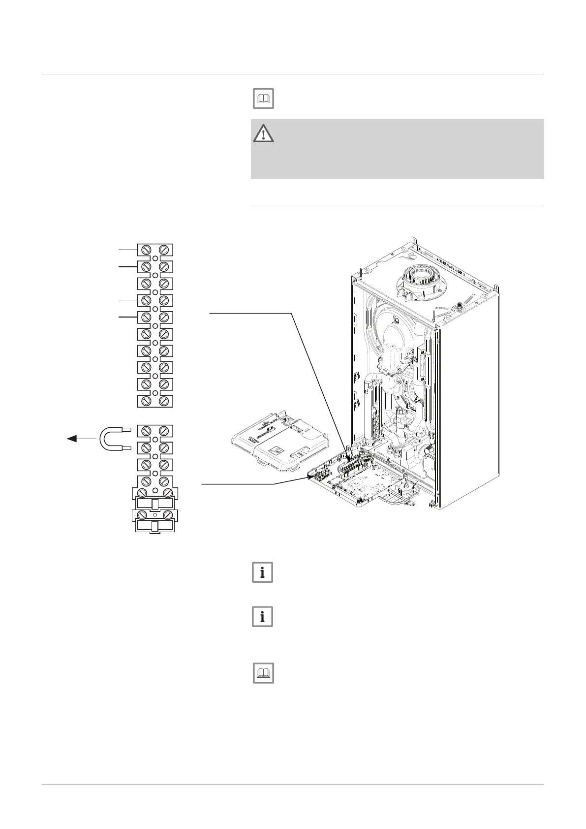
6.4.1 Making the electrical connection
Fig.33 Remove terminal cover
PN-0000395
1
2
3
4
5
6
7
8
9
1
0
1
2
3
4
5
G
H
M2
M1
Outdoor
Weather
Sensor
Low Voltage
Controls
(OpenTherm)
Important
When fitting external controls remove the yellow link wire from the
Mains Terminal Block M1.
Important
Consideration must be given to Health and Safety Document 635
(The Electricity at Work Regulations, 1989).
1. Remove the front panel.
See
Specific maintenance instructions, page 51 to remove the front
panel.
2. Hinge down the control box and unclip the terminal block cover.
3. Slacken both gland nuts in the bottom of the boiler lower panel and
insert the mains cable and the external control system cable through
them.
4. Leave sufficient slack in the cables to allow the control box to be
hinged fully open. Tighten both gland nuts.
6 Installation

 Loading...