I
M
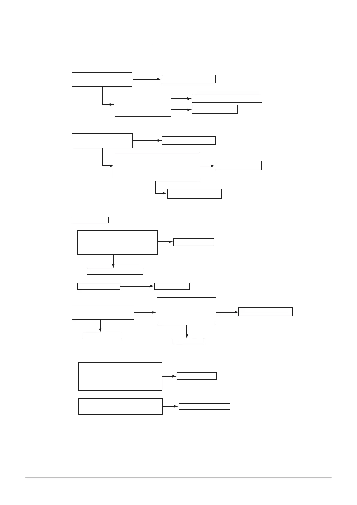
Temperature sensors faulty.
Cold resistance approximately
10k Ω @ 25° C (CH sensor)
20k Ω @ 25° C (Flue sensor)
(resistance reduces with increase in temp.)
NO
Replace sensor
YES
If pump is running the heat exchanger
could be obstructed
Replace heat exchanger
1.
2.
Replace hydraulic pressure switch
YES
Restore system pressure
YES
NO
CH system pressure less than
0.5 bar
Check wiring and PCB - X22
connector for approx. 5V DC
between green & black - see
Wiring Diagram
Replace PCB
NO
J
Replace sensor
NO
System fault - correct
NO
YES
Ensure that the boiler and
system are fully vented
Check flow temperature sensor connections
and position.
Cold resistance approximately
10k Ω @ 25° C (CH sensors)
(resistance reduces with increase in te
mp.)
YES
Go to section ‘B’
K
Is there 230V at:
Diverter valve motor Replace motor
1.
YES
PCB - X13 connector terminals between:-
Blue & Black (central heating mode)
Blue & Brown (domestic hot water mode)
see Wiring Diagram
Replace PCB
2.
NO
Check diverter valve cable
YES
L
YES
NO
Replace PCB
Replace Hall Effect Sensor
Is mains water filter & assembly
clean, and rotor moving freely ?
Clean or replace
NO
Check wiring and PCB - X22
connector for approx. 5V DC
between red & blue from Hall
Effect sensor -
see Wiring Diagram
YES
PN-0000319

 Loading...