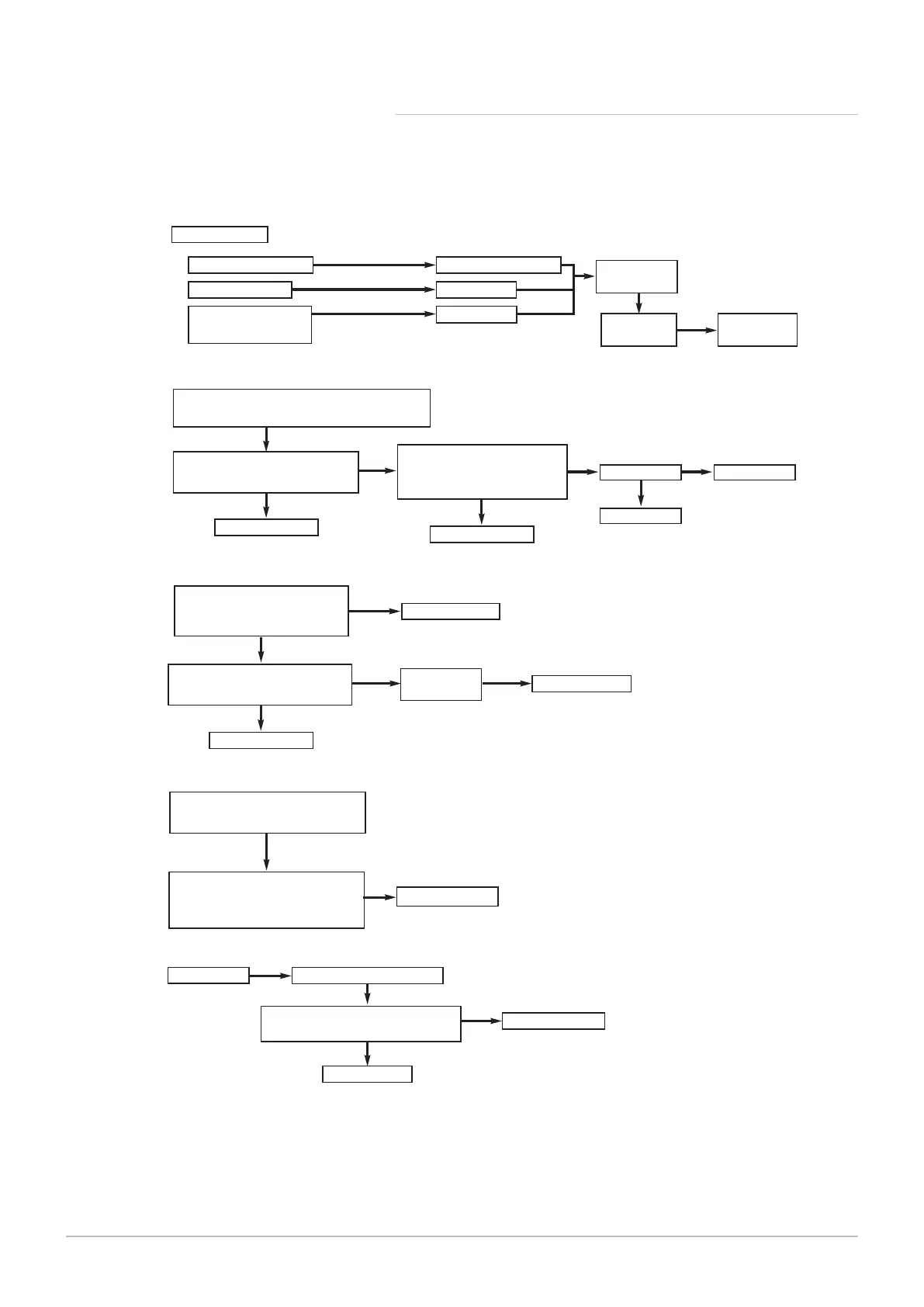
Is there 230V at:
Main terminals L and N
Check electrical supply
1.
NO
Main terminal fuse
Replace fuse
Display
illuminated
2.
NO
PCB - X10 connector
Main terminals L and N
Check wiring
3.
NO
NO
A
B
C
NO
Fan connections correct at fan &
PCB X11 and X23 connectors -
see Wiring Diagram
Make connections
Fan jammed or
faulty wiring
Connection
OK at X41
Display or
Main PCB fault
Switch to DHW mode maximum flow and press reset.
During next 3 minutes check:-
230V at PCB - X13 connector
(between blue & brown - see Wiring
Diagram)
NO
Replace PCB
YES
230V between PCB - X13
connector (blue) and PCB - X11
connector (black) - see Wiring
Diagram
NO
Replace PCB
YES
230V at pump
YES
Replace pump
NO
Check wiring
YES
NO
Replace PCB
Replace fan or wire
YESYES
Temperature sensor faulty.
Check correct location and wiring.
NO
D
Replace sensor
Cold resistance approximately
10kΩ @ 25° C (DHW and CH sensors)
(resistance reduces with increase in
temp.)
YES
Gas at burner
Ensure gas is on and purged
Replace PCB
Replace gas valve
Check wiring and PCB - X36 connector
see Wiring Diagram
YES
NO
NO
E
230V at PCB - X11 connector
(between blue & brown - see Wiring
Diagram)
PN-0000317

 Loading...