Powered by Safety
®
12
Equipment Description
Power/Vac® Metal-Clad Switchgear 5kV & 15kV
01.4IB.67000
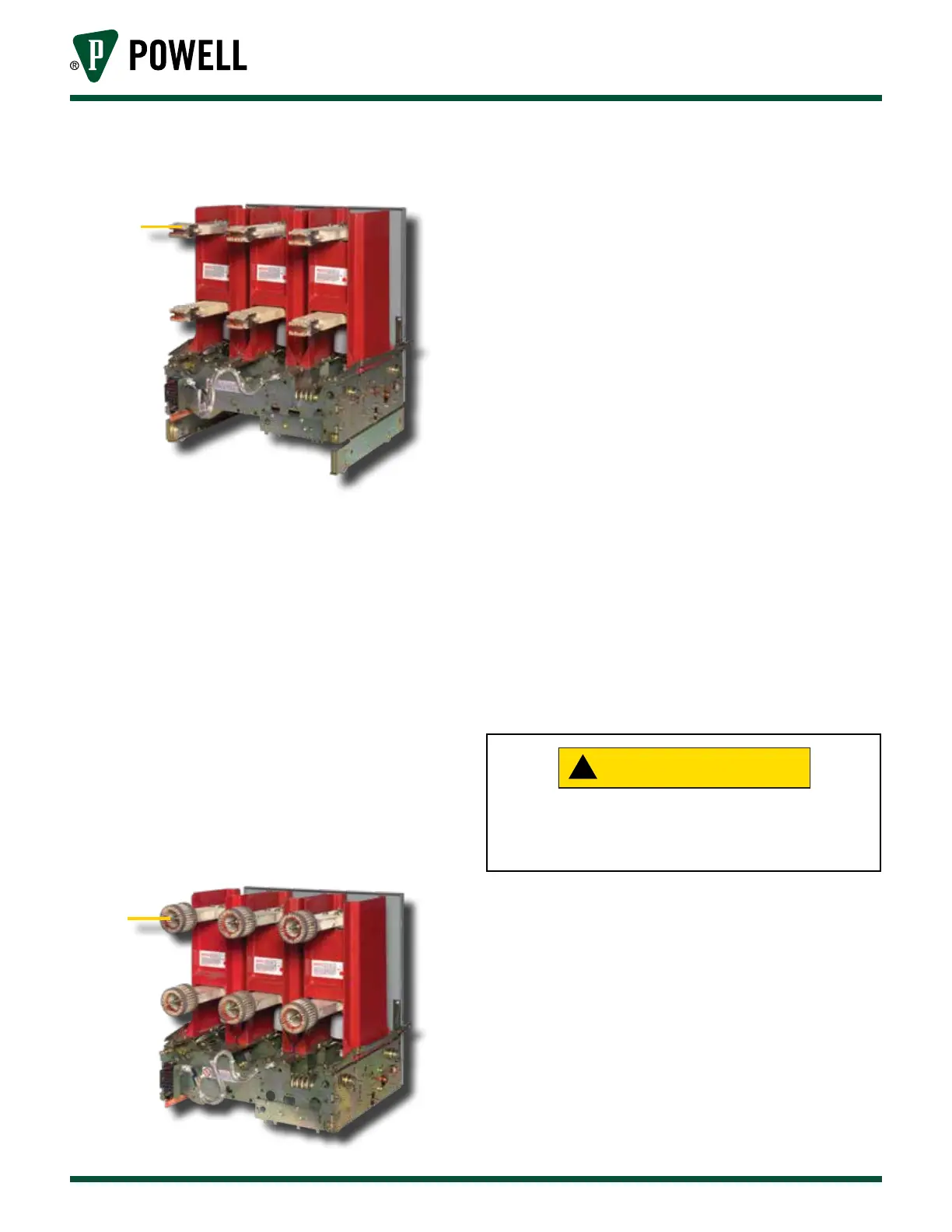
Figure 4 Primary Disconnecting Device -
1200A
a
a. Primary Disconnecting Device
On 3000A primary disconnects, silver-plated
copper fingers are positioned in a circular
configuration and are supported by a
non-magnetic spider. This spider spaces the
fingers equally around the breaker stud and
fastens them to the end of the stud. The
fingers are held in contact with the breaker
stud by a stainless steel garter spring. A second
garter spring on the outer end of the finger
provides contact pressure when the finger
assembly is connected to the tube in the
metal-clad unit (Figure 5).
Figure 5 Primary Disconnecting Device -
3000A
a
a. Primary Disconnecting Device
K. BUS COMPARTMENT
The main buses are enclosed in a metal
compartment with removable front covers to
provide accessibility. The bus is supported and
insulated by molded glass-reinforced polyester
barriers which are flame retardant and track
resistant. Polyester supports with porcelain
sleeves may be furnished as an option in 5kV
and 15kV equipment.
Bus bars are insulated with an extruded
thermoplastic insulation sleeving or an
applied epoxy insulation using the fluidized
bed process. All bolted joints have
silver-to-silver connections for low contact
resistance. Most joints are insulated with a
molded polyvinyl chloride boot.
L. CURRENT TRANSFORMER COMPARTMENT
Current transformers are mounted over the
primary bushings in the rear of the breaker
compartment and are isolated from the breaker
by the shutter barrier. They are front accessible
by removal of the shutter barrier.
!
The equipment must be deenergized before
any component is touched or serious injury
could result.
M. PRIMARY TERMINATION SPACE
The primary termination space of each breaker
unit is isolated from the other equipment
by metal barriers. Space is provided in this
compartment for connecting the customer’s
primary cable by means of potheads or clamp
type terminals. Two-hole NEMA drilling for
two cables per phase is provided at all cable
connection points.