Powered by Safety
®
33
Installation
01.4IB.67000
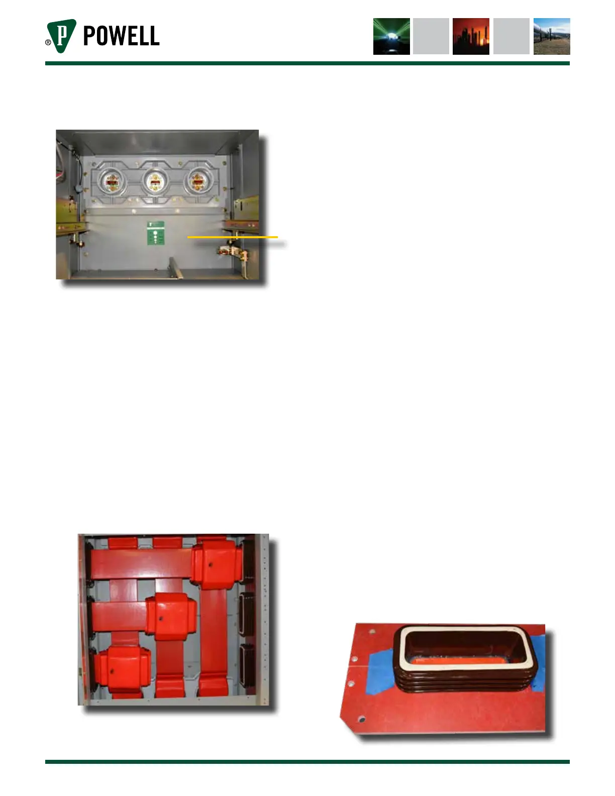
Figure 19 View of Typical Front Lower PT/CPT
Rollout Compartment
a
a. Barrier
c. Remove the vertical mid barrier located
in the lower part of the front upper
compartment. This barrier is located
approximately 49 inches from the front
of the stack (Figure 15, b).
d. Do not remove the secondary
disconnect block (Figure 15, c) or the
chain (Figure 15, a). This barrier can be
removed by sliding it down. This will
expose the main bus compartment as
shown in Figure 20.
Figure 20 View of Main Bus Compartment from
Front
e. Unbolt and remove the glastic shipping
supports taking care to ensure that
splice plates and spacers provided in
the bus joint do not fall off. Loosely
refasten bus hardware to hold the splice
plates and spacers in place.
f. Discard the shipping supports. The
red insulating boots will have to be
removed to access the bolts for the
shipping supports. The boots are held
together using plastic reusable pull
apart fasteners.
g. Remove inter-unit bus supports. (Go to
step ii if polyester glass bus supports are
provided).
i. Apply a strong adhesive tape to
keep the two glastic supports
together temporarily. The tape may
be applied in four places - above,
below, and between the porcelain
bus supports (Figure 21).
ii. Remove the / - 20 fasteners used to
mount the bus support to the side
sheet. There should be 4 (2 for poly
glass) on the top and 4 (2 for poly
glass) at the bottom. The hex nuts
should be towards the outside on
the left hand side of the side sheet.
iii. Gently remove the bus support
assembly away from the side sheet
and into the bus compartment.
Let it rest temporarily in a
vertical position inside the bus
compartment.
Figure 21 Location of Tape