Powered by Safety
®
42
Installation
Power/Vac® Metal-Clad Switchgear 5kV & 15kV
01.4IB.67000
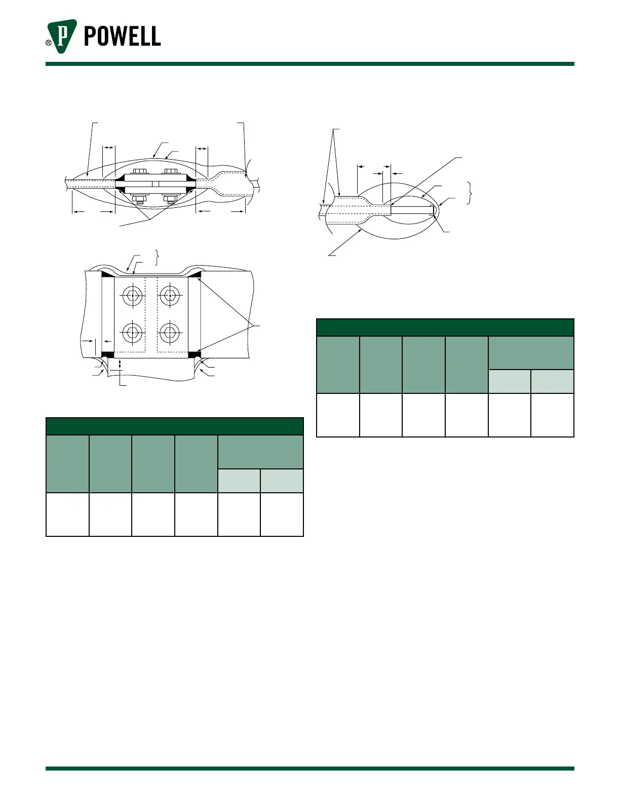
Figure 33 Tee Connection Joint
+
+
+
+
Epoxy Insulation Thermoplastic Sleeving
or Tape Insulation
.50 (12.7)
Min
.50 (12.7)
Min
“A”
“B”
“C”
“C”
“B”
“A”
Overlap Tape in a
Figure Eight Pattern
RB Putty *
Both Ends
RB Putty *
Both Ends
.50 (12.7)
Min
“A”
“A”
“B”
“B”
.50 (12.7)
Min
Table H Insulation of Tee Connection Joint
Insulation
Level (kV)
Inner Filler
“A”
Outer Wrap
“B”
“C”
(inches)
Approx. Number of
Rolls per Joint of HV
Tape ∆
2” or 3”
Bars
4” or 6”
Bars
5 or 15
RB Putty* &
3 Layers HV
Tape ∆
2 Layers
HV Tape ∆
3
/ Roll RB
Putty *
1 Roll HV
Tape ∆
1 Roll RB
Putty *
2 Rolls HV
Tape ∆
Note: * Electrical grade rubber based putty
0282A3529 P008 in roll form will be
used to grade voids and smooth out
sharp edges of joints. This putty has
no insulation value.
1 roll is /” x 1½” x 5’ long.
∆ HV Tape 0282A3529 P004 roll
is .030” x 2” x 30’ long. Apply with
mastic side down.
Figure 34 Dead End Bus Joint Insulation
“C”
Min
50 (12.7)
Min
“B” Layers - 1/2 LAP
Pre-Insulation Epoxy Insulation
Thermoplastic Sleeving or Tape Insulation
Apply RB Putty Sparingly
to Grade-Out and Round O
Pre-Insulation
“A”
“B”
Crisscross Tape in a
Figure Eight Pattern to
Fully Cover End
1) Cut and Apply 1-Strip of
Tape to Form a Boot Over End
2) Apply RB Putty Sparingly
to Round O End of Bar
3) Continue with “A” Layer
of HV Tape.
Table I Insulation of Dead End Bus Joint
Insulation
Level (kV)
Inner Filler
“A”
Outer Wrap
“B”
“C”
(inches)
Approx. Number of
Rolls per Joint of HV
Tape ∆
2” or 3”
Bars
4” or 6”
Bars
5 or 15
RB Putty* &
3 Layers HV
Tape ∆
3 Layers
HV Tape ∆
3
/ Roll RB
Putty *
/ Roll HV
Tape ∆
/ Roll RB
Putty *
1 Roll HV
Tape ∆
Note: * Electrical grade rubber based putty
0282A3529 P008 in roll form will be
used to grade voids and smooth out
sharp edges of joints. This putty has
no insulation value.
1 roll is /” x 1½” x 5’ long.
∆ HV Tape 0282A3529 P004 roll
is .030” x 2” x 30’ long. Apply with
mastic side down.