Powered by Safety
®
38
Installation
Power/Vac® Metal-Clad Switchgear 5kV & 15kV
01.4IB.67000
3. Sixteen sets of 0.38 x 1” hardware is
provided for perimeter bolting. The
following guidelines shall be followed:
a. Minimum of 3 bolts on each vertical
post.
b. For 82” deep and 94” deep stacks,
a minimum of two bolts on each
depth post with at least one bolt in
the front compartment and one bolt
in the rear compartment.
c. For 106” deep stacks, a minimum
of three bolts on each depth post
with at least one bolt in the front
compartment and one location in
the rear compartment.
Where there are no accessibility issues it
is generally recommended that perimeter
bolting be done at all 16 locations.
Note: If the units have to be moved or lifted
after installation, they should be lifted
only at the shipping splits
L. CONNECTIONS
1) Main Bus Bars
The main bus bars and other connection
bars are either copper or aluminum. The
connection surfaces are silver surfaced
or equivalent. The silver plating used on
bolted contact surfaces is approximately
0.0001” thick; plating on sliding contact
surfaces is thicker. All field assembled joints
in primary conductors should be made as
follows:
1. Wipe the surface clean with a lint-free
cloth. Do not use sandpaper or any
other abrasive material on the plated
surface. Avoid handling of cleaned
surfaces as much as possible. If the
surface is tarnished, clean it with silver
polish and then wash it with denatured
alcohol.
2. Join the clean contact surfaces by using
the hardware provided.
The correct length of bolt must be
used in each joint to ensure that
electrical clearances at bolt locations
are maintained. As a general rule,
when using / inch diameter bolts, the
bolts should be 1 inch longer than the
combined thickness of the copper bars
being bolted together.
For example, if three / inch thick
copper bars are to be connected,
the bolt should be 1/ inch long In
addition to proper length bolts the bolt
assembly must include flat washers split
ring lock washers and nuts All bus joint
hardware is zincplated dichromate
treated high strength steel Cap screws
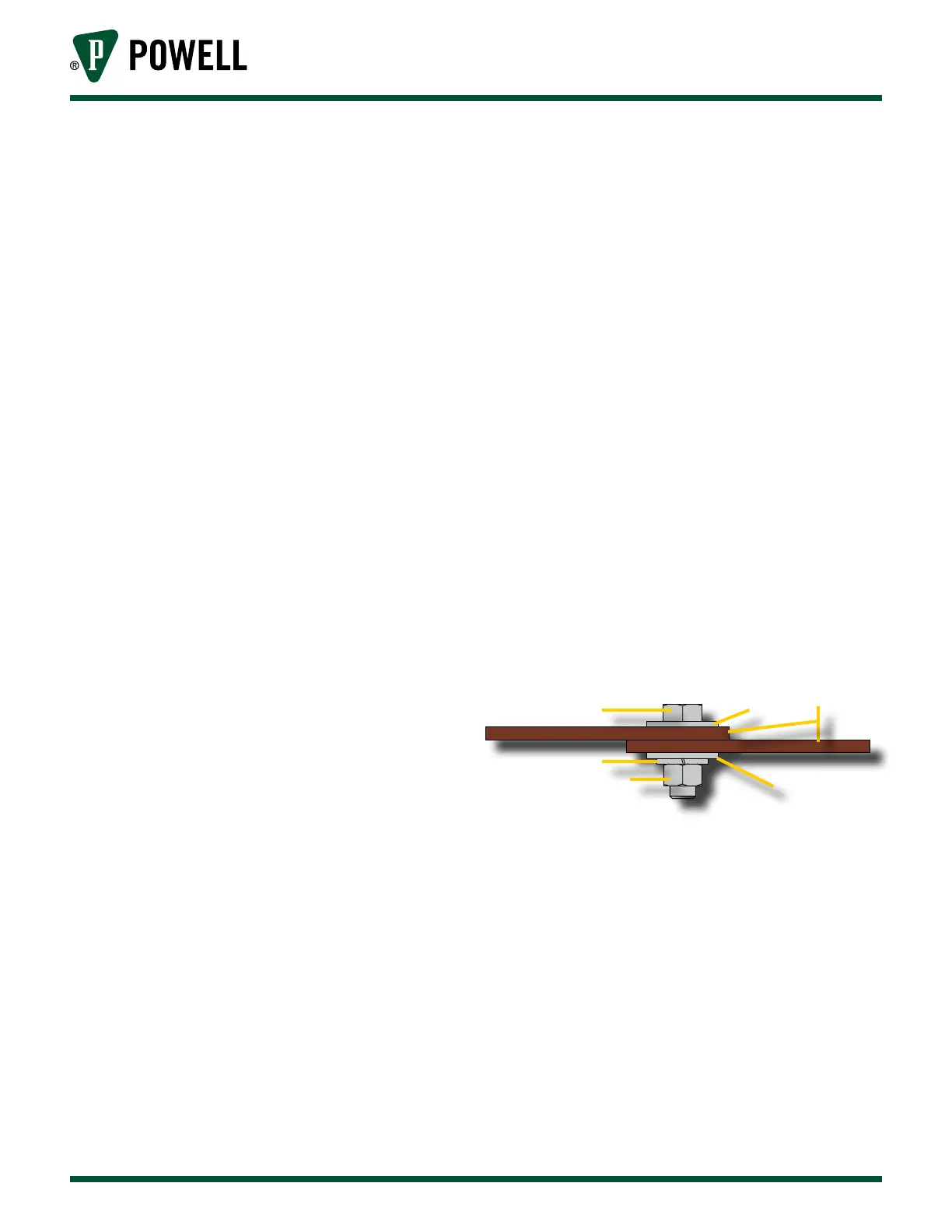
are / - 13 SAE Grade 5. See Figure 29
for proper hardware assembly.
Figure 29 Ground Bus Splice Bolt Assembly
a
b
b
c
d
e
a. Bolt
b. Flat Washer
c. Bus Bar
d. Split Lock Washer
e. Nut
3. In some cases, external connections are
made to metal-clad switchgear bus by
bars. The metal-clad switchgear bars
are normally silver plated. Unplated
bars, either copper or aluminum, should
not be used to connect to plated bars.
4. All field assembled primary conductor
joints and terminations must be