Powered by Safety
®
57
Operation
01.4IB.67000
J. KEY LOCKS
On the left side breaker racking mechanism
track is a provision for a key lock
(Figure 41, j). The purpose of this lock is to
keep the breaker from closing in the “Test” and
“Connect” positions by operating the negative
interlock. To remove the key, push slide to the
rear and extend the bolt of the lock into slot.
This allows the key to be removed and prevents
the breaker from closing. The key lock does not
prevent motion of the racking mechanism.
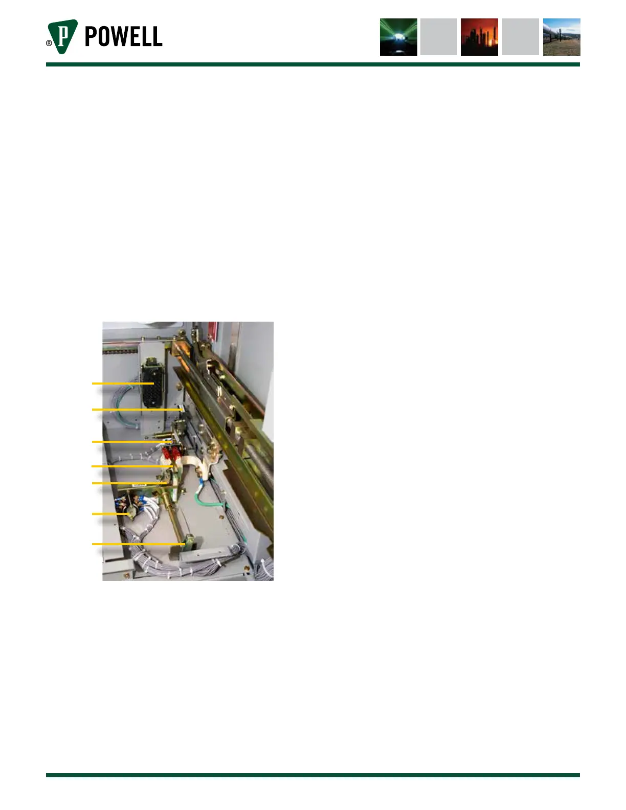
Figure 43 Stationary Auxiliary Switch & Circuit
Breaker Position Indicator
a
b
c
d
e
f
g
a. Secondary Coupler
b. Position Switch Actuator
c. Position Switch
d. Ground Shoe
e. Station Auxiliary Switch Connect
Position Actuator
f. Stationary Auxiliary Switch
g. Stationary Auxiliary Switch Test
Position Actuator
K. PADLOCKS
Two positions for a possible 3 padlocks each
are provided on the racking mechanism. The
front position keeps the breaker from closing in
the “Test” and “Connect” position. To obtain this
position push slide to the rear and insert the
padlock in the slotted opening just forward of
the key lock. This gives the same interlocking
functions as the key lock and does not block
the motion of the racking mechanism.
The second position for padlocks is behind the
key lock. A padlock in this slot will prevent any
motion of the racking mechanism by keeping
the hexagon turning shaft covered.
L. STATIONARY AUXILIARY SWITCH
An auxiliary switch can be provided at the
bottom of the breaker compartment so that
additional contacts can be actuated by the
operation of the breaker. The breaker will
operate this switch when it is in the “Test” or
“Connect” position (Figure 43).
M. BREAKER POSITION SWITCH
A position switch can be provided at the
bottom of a breaker compartment so that it will
be operated by a bracket on the breaker frame
when the breaker is in the “Connect” position.
When the breaker is withdrawn, a spring will
return the switch to its normal position
(Figure 43).
N. SPACE HEATERS
Space heaters are provided in all outdoor
switchgear in order to keep the inside
temperature several degrees higher than the
outside. Heaters are also furnished for indoor
switchgear when it is known that abnormal
atmospheric conditions exist at the installation,
or when specified by the customer.