Powered by Safety
®
32
Installation
Power/Vac® Metal-Clad Switchgear 5kV & 15kV
01.4IB.67000
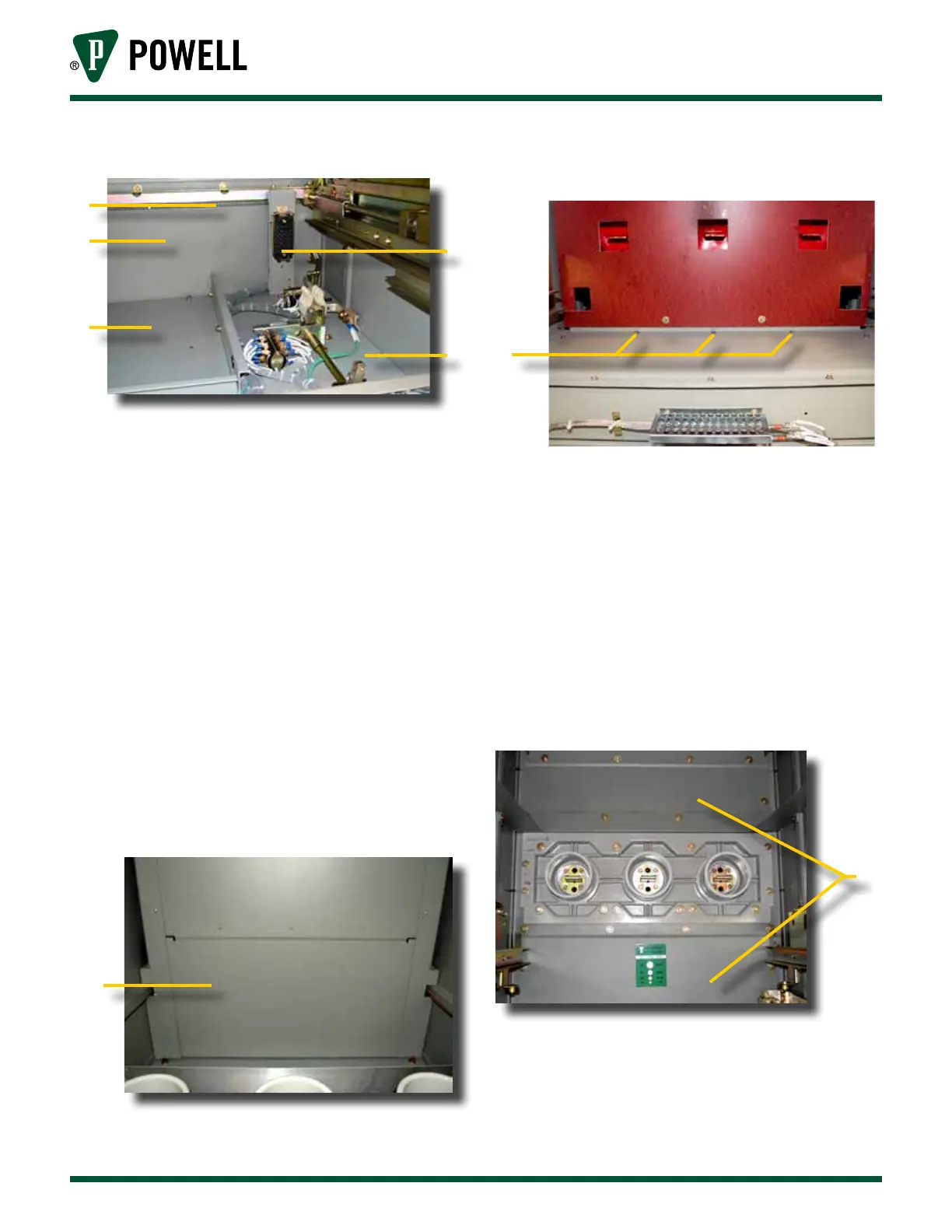
Figure 15 Front Upper Compartment
a
b
d
c
e
a. Chain
b. Vertical Mid Barrier
c. Secondary Disconnect Block
d. Horizontal Barrier
e. Pan
For stacks that have a two-high PT/CPT
tray in the front upper compartment,
the procedure for removing the
horizontal barrier is different from that
shown above. For such stacks, remove
the three Taptites (self threading bolts)
shown in Figure 17 in the front upper
compartment. When these taptites are
removed, the barrier underneath
(Figure 16, a) can be removed.
Figure 16 View Looking Up Into Front Bottom
Compartment of a 2-High
a
a. Barrier
Figure 17 Taptite Location in Front Upper
Compartment
a
a. Taptites (3)
Remove the vertical mid barrier
located in the upper part of the
lower front of the stack. See
Figure 18 for identification of barrier in
the breaker compartment and Figure 19
for identification of barrier in a PT/CPT
rollout compartment.
Figure 18 View of Typical Front Lower Breaker
Compartment
a
a. Barriers