Powered by Safety
®
46
Installation
Power/Vac® Metal-Clad Switchgear 5kV & 15kV
01.4IB.67000
Figure 37 Rear View of Unit Showing Ground
Fault Current Transformer
a
a. Ground Fault Current
Transformer (Through-Type)
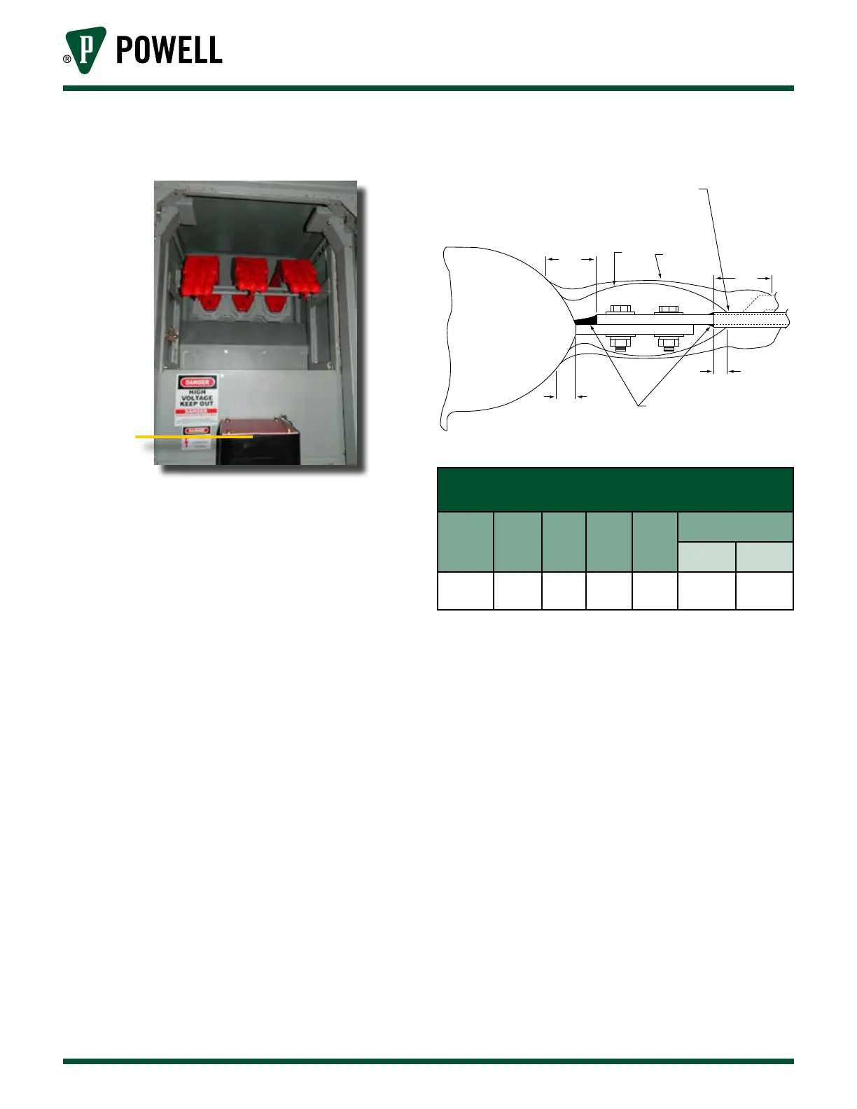
Figure 38 Bar-Type Current Transformer Joint
Insulation
Pre-Insulation Epoxy insulation
Thermoplastic Sleeving or
Tape Insulation
“D”
“A” “B”
1/2 LAP
“C”
.50 (12.7)
Min
.75 (19.11)
Min
RB Putty *
C.T.
Table K Bar-Type Current Transformer
Joint Insulation
Insulation
Level (kV)
Inner
Filler
“A”
Outer
Wrap
“B”
“C”
(inches)
“D”
(inches)
Approx. No. of Rolls per
Joint of HV Tape ∆
2” or 3”
Bars
4” or 6”
Bars
5 or 15
3 Layers
HV Tape ∆
2 Layers
HV
Tape ∆
3 3 ‡
/ Roll HV
Tape ∆
1/ Rolls HV
Tape ∆
Note: * Electrical grade rubber base putty
0282A3529P008 in roll form will be
used to grade voids and smooth out
sharp edges of joints. This putty has
no insulation value.
1 roll is /” x 1½” x 5’ long.
‡ Insulate as far as possible. Do not
cover polarity marks.
∆ HV Tape 0282A3529P004 roll is
.030” x 2” x 30’ long. Apply with
mastic side down.