3300 ACM Installation and Operation Manual Power Measurement Ltd.
2-2 Installation
NOTE
It is very important that communications
wiring be made to the RS-485 port of ev-
ery 3300 ACM being installed. See section
2.6 for detailed instructions on communi-
cations connections.
2.3 POWER SUPPLY
CONNECTIONS
Power Supply Options
The basic model 3300 ACM can be powered by 108 to 132
VAC/47 to 66 Hz at 0.25 Amps. A number of power supply
options are also available. The label on the base module
indicates if the unit is equipped with one or more of these
options.
P240 OPTION
This option can be powered by 216 to 264 VAC/47 to 66 Hz
at 0.125 Amps.
P24 OPTION
This option can be powered by 22 to 27 VDC at 0.3 Amps.
P120DC OPTION
This option can be powered by 85 to 132 VAC at 47 to 440
Hz or 110 to 170 VDC, both at 0.1 Amps.
P240DC OPTION
This option can be powered by 85 to 264 VAC at 47 to 440
Hz or 110 to 340 VDC, both at 0.1 Amps. Note that units
equipped with this option are supplied with an overheight
base module enclosure (see Appendix A for dimensions).
Power Sources and Connections
The basic model or P240 option can be powered from a
dedicated fused feed, or from the voltage source which it is
monitoring, as long as it is within the supply range. The
P24 option must be powered from a dedicated fused feed. If
an AC power supply is being used, connect the line supply
wire to the 3300 ACM L/+ terminal and the neutral supply
wire to the N/- terminal. If a DC power supply is being
used, connect the positive supply wire to the 3300 ACM L/+
terminal and the negative (ground) supply wire to the N/-
terminal.
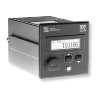
NOTE
The 3300 ACM -TRAN model does not
provide a display module. All data must
be accessed via the communications port
of the base module. Refer to Appendix G.
The base module of the 3300 ACM can be mounted flush
against any flat surface. The unit provides four slots on its
mounting flange for this purpose. The base module is
typically mounted inside the switchgear cabinet. Labelling
on the base module has been positioned to allow the module
to be mounted against a wall with the terminal strip in a
vertical orientation. However, the module can be mounted
in whichever orientation is most convenient.
WARNING
The base module can be mounted on the
door of the switchgear cabinet; however,
some electrical codes may prohibit ex-
tending voltages greater than 120 VAC
line-to-neutral or 208 VAC line-to-line to
the door. If this is the case, mount the
base module inside the cabinet as de-
scribed above, or use the 3300 ACM with
PTs that provide 120 VAC secondaries
(see Section 2.5).
Note that the distance between the mounting locations of
the display and base modules will be limited by the length of
the interconnecting display cable (6 feet / 1.82 meters).
2.2 GENERAL WIRING
CONSIDERATIONS
Connections to the 3300 ACM are made to the terminal strip
located on the base module. Appendix A provides terminal
block dimensions. 12 AWG
(4mm
2
) to 14 AWG (2.7mm
2
)
gauge wire is recommended for all electrical connections.
Ring or spade terminals may be used to simplify connection.
CAUTION
All wiring must conform to all applicable
local electrical codes.
Courtesy of NationalSwitchgear.com
 Loading...