3300 ACM Installation and Operation Manual Power Measurement Ltd.
G-2 Appendix G: Serial Communications Protocol
2.2.3 ADDRESS INFORMATION FIELD
The Address Information field is fixed in length and contains
the following two sub-fields:
1) SOURCE ADDRESS (2 Bytes)
These two bytes contain the address of the device from
which the packet originated.
2) DESTINATION ADDRESS (2 Bytes)
These two bytes contain the address of the device to
which the packet is being sent.
2.2.4 DATA FIELD
The Data Field will vary in length (0 to 251 Bytes) according
to the type of message contained within the packet.
DATA REGISTERS
All information passed to and from the meter within the data
field is in the form of registers. Each register is represented by
4 bytes. Three of the bytes contain the metering data or setup
data. Byte 4 of each data register represents the low order byte
of the 16 bit address where the register is located.
BYTE 1 BYTE 2 BYTE 3 BYTE 4
Data Bits Data Bits Data Bits Low order register
0 to 7 8 to 15 16 to 23 address byte
For example, a 4 byte value of 3C,06,00,21 hex would indicate
that register 0021hex (which is total kW) has a value of
00063C hex (or 1596 kW in decimal).
REGISTER ADDRESSES
Each piece of metering data, as well as each setup parameter,
is assigned a unique 16 bit register address. For example, total
kW is located at register address 0021 hex (or 33 decimal).
The current scale parameter is located at 0A03 hex (or 2563
decimal).
The low order byte of the register address is represented by
Byte 4 of the register. The high order byte of the address
represents the register page.
REGISTER PAGES
Data registers are grouped in pages. The most significant (high
order) byte of the register address indicates the page within
which the register resides. The page in which a register is
located is an indication of the nature of that register:
Page 0: real time metering data
Page 1: minimum values
Page 2: maximum values
Page 10: meter setup parameters
A complete list of register addresses is provided in Figures G-
3a and G-3d.
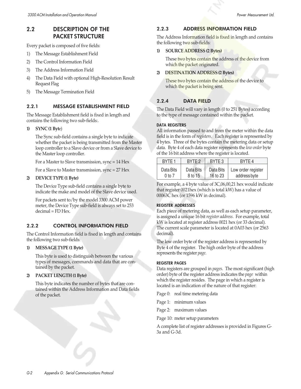
2.2 DESCRIPTION OF THE
PACKET STRUCTURE
Every packet is composed of five fields:
1) The Message Establishment Field
2) The Control Information Field
3) The Address Information Field
4) The Data Field with optional High-Resolution Result
Request Flag
5) The Message Termination Field
2.2.1 MESSAGE ESTABLISHMENT FIELD
The Message Establishment field is fixed in length and
contains the following two sub-fields:.
1) SYNC (1 Byte)
The Sync sub-field contains a single byte to indicate
whether the packet is being transmitted from the Master
loop controller to a Slave device or from a Slave device to
the Master loop controller.
For a Master to Slave transmission, sync = 14 Hex
For a Slave to Master transmission, sync = 27 Hex
2) DEVICE TYPE (1 Byte)
The Device Type sub-field contains a single byte to
indicate the make and model of the Slave device used.
For packets sent to/by the model 3300 ACM power
meter, the Device Type sub-field is always set to 253
decimal = FD Hex.
2.2.2 CONTROL INFORMATION FIELD
The Control Information field is fixed in length and contains
the following two sub-fields:
1) MESSAGE TYPE (1 Byte)
This byte is used to distinguish between the various
types of messages, commands and data that are con-
tained by the packet.
2) PACKET LENGTH (1 Byte)
This byte indicates the number of bytes that are con-
tained within the Address Information and Data fields
of the packet.
Courtesy of NationalSwitchgear.com
 Loading...