3300 ACM Installation and Operation Manual Power Measurement Ltd.
2-12 Installation
2.6 COMMUNICATIONS
CONNECTIONS
The 3300 ACM is equipped with an RS-485 communications
port. Optical coupling provides full isolation between the RS-
485 communication lines and the metering equipment.
Connections are made to the RS-485 terminals on the main
terminal strip.
NOTE
It is very important that communications
wiring be made to the RS-485 port of every
3300 ACM being installed, even if remote
communications are not initially required.
All field service work including running
diagnostics, testing, software upgrades,
feature upgrades, etc., are performed via
the communications link.
The following sections describe wiring requirements for
connection with a master computer station or other device.
Refer to Chapter 5 for information regarding communications
setup parameters.
RS-485 Connections
RS-485 communications allows multiple devices to be con-
nected on the same bus. Up to 32 devices can be connected
on a single RS-485 bus, which consists of a shielded twisted
pair cable. The overall length of the RS-485 cable connecting
all devices cannot exceed 4000 feet (1219 meters).
To connect an RS-485 communications bus to a computer or
other RS-232C equipped device, an RS-232C to RS-485
converter is required, such as Power Measurement’s COM32
or COM128. The COM32 offers a single RS-485 port, while
the COM128 offers a total of four RS-485 ports that can each
support up to 32 devices.
General Bus Wiring Considerations
Devices connected on the bus, including the 3300 ACM,
converter(s) and other instrumentation, must be wired as
follows:
a. Use a good quality shielded twisted pair cable for each
RS-485 bus. It is recommended that 22 AWG (0.4 mm
2
)
or larger conductor size be used.
b. Ensure that the polarity is correct when connecting to the
RS-485 port (+) and (-) terminals of each device.
c. The shield of each segment of the RS-485 cable must be
connected to ground at one end only.
CAUTION
Do not connect ground to the shield at
both ends of a segment. Doing so will al-
low ground loop currents to flow in the
shield, inducing noise in the communica-
tions cable.
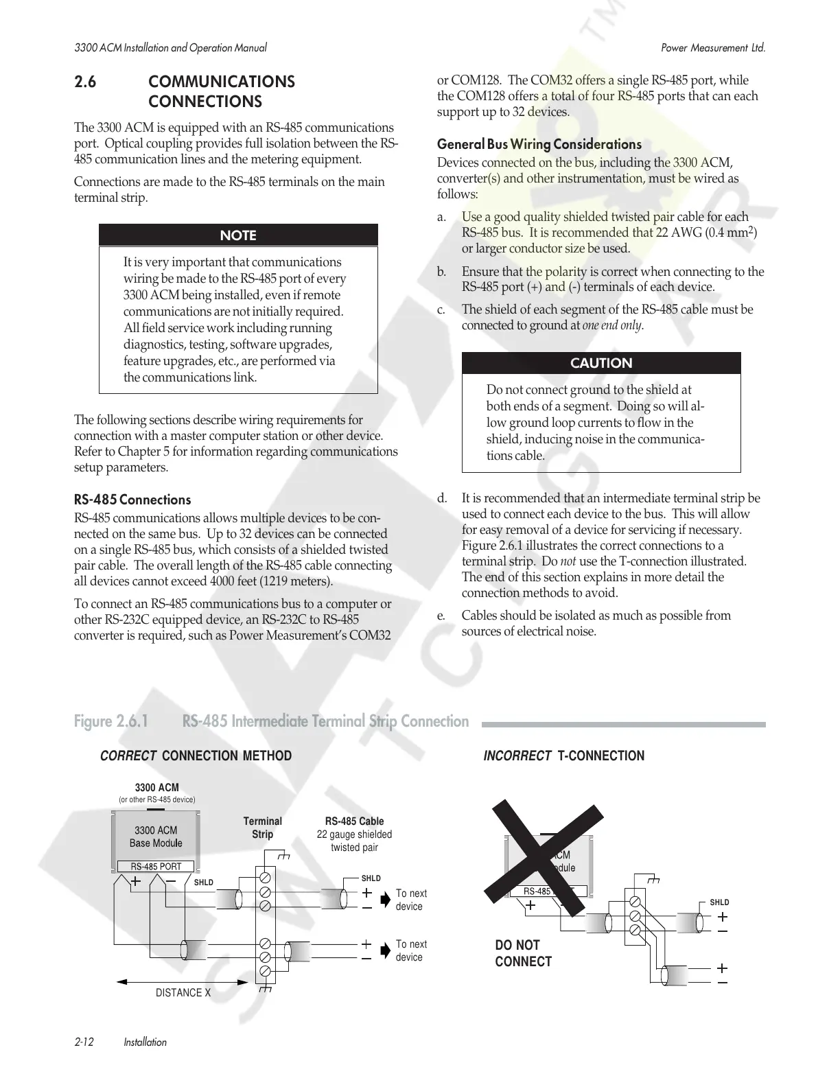
d. It is recommended that an intermediate terminal strip be
used to connect each device to the bus. This will allow
for easy removal of a device for servicing if necessary.
Figure 2.6.1 illustrates the correct connections to a
terminal strip. Do not use the T-connection illustrated.
The end of this section explains in more detail the
connection methods to avoid.
e. Cables should be isolated as much as possible from
sources of electrical noise.
SHLD
SHLD
Terminal
Strip
DISTANCE X
To next
device
To next
device
RS-485 Cable
22 gauge shielded
twisted pair
SHLD
INCORRECT
T-CONNECTION
CORRECT
CONNECTION METHOD
DO NOT
CONNECT
3300 ACM
(or other RS-485 device)
Figure 2.6.1 RS-485 Intermediate Terminal Strip Connection
Courtesy of NationalSwitchgear.com
 Loading...