3300 ACM Installation and Operation Manual Power Measurement Ltd.
vi
List of Figures
2. INSTALLATION
2.1.1 Environmental Guidelines for Installation ................................................................ 2-1
2.5.4a 4 Wire Wye: 3 Element Direct Connection (For 120/208 to 347/600 Volt Systems). 2-5
2.5.4b 4 Wire Wye: 3 Element Connection Using 3 PT's .................................................... 2-6
2.5.4c 4 Wire Wye: 2½ Element Connection Using 2 PT's ................................................. 2-7
2.5.4d 3 Wire Wye: 3 Element Direct Connection (For 120/208 to 347/600 Volt Systems). 2-8
2.5.5a 3 Wire Delta: 2½ Element Using 2 PT’s and 3 CT’s ................................................ 2-9
2.5.5b 3 Wire Delta: 2 Element Using 2 PT’s and 2 CT’s ................................................. 2-10
2.5.6 3 Wire Single Phase: 2 Element Direct Connection ............................................... 2-11
2.6.1 RS-485 Intermediate Terminal Strip Connections .................................................. 2-13
2.6.2 RS-485 Communications Connections .................................................................. 2-14
2.6.3 RS-485 Topologies to Avoid .................................................................................. 2-15
2.7.1 kWh Pulse Output Connections............................................................................. 2-16
3. OPERATION
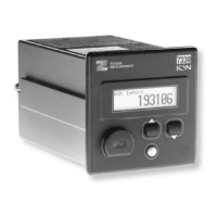
3.3.1 3300 ACM Front Panel Displays ............................................................................. 3-2
3.3.2 3300 ACM Display Module Front Panel Features .................................................... 3-3
3.4.3 Programming Mode Display and Button Functions .................................................. 3-5
3.4.5 Field Programming Example ................................................................................... 3-7
3.4.6a Programmable Operating Parameters I .................................................................... 3-8
3.4.6b Programmable Operating Parameters II ................................................................... 3-9
4. MEASURED PARAMETERS
4.1.1a List of Measured Parameters .................................................................................. 4-2
4.1.1b List of Measured Parameters .................................................................................. 4-2
4.3.1 Thermal Demand Calculation ................................................................................... 4-5
4.3.4 Power Reading Polarities ......................................................................................... 4-8
5 COMMUNICATIONS
5.2.1 Remote Communication Methods ............................................................................ 5-1
5.8.1 Modbus Communications Connections .................................................................... 5-5
5.9.1 PLC/AB Communications Connections ................................................................... 5-7
Courtesy of NationalSwitchgear.com
 Loading...