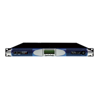
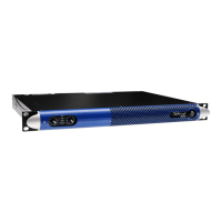
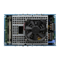
3
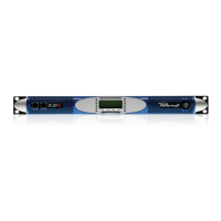
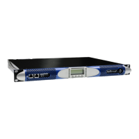
K2 K3 | SERVICE MANUAL
Index:
1. Service repairing kit 4
2. Opening the amplier cover 5
3. Discharging the amp capacitors 5
4. Troubleshooting 7
5. Removing the power supply board 9
PSU Fault Finding 17
Final Inspection 21
6. Removing the amplier output board 26
AMP outputboard Fault Finding 33
Final Inspection 34
7. Removing the fan 37
8. Removing the display 38
9. Firmware update procedure 40
10. Removing the control board (k-cntrl) 43
Menu Diagrams 44
11. Copying the PAM les from a Virtual Machine 46
12. Error codes 47
13. Internal LEDs check 48
14. Repair Kit List 49
15. Mechanical parts 49
16. Replacement Boards 50
KDSP Board Installation 51
KAESOP Board Installation 52
CAUTION
RISK OF ELECTRICK SHOCK
DO NOT OPEN
WE RECOMMEND THAT ALL SERVICE OPERATIONS
ARE CARRIED OUT BY A TECHNICIAN IN THE MANNER
DESCRIBED IN THIS GUIDE.
IF NOT EXPLICITLY STATED OTHERWISE, DISCONNECT THE
AMPLIFIER FROM THE MAINS BEFORE OPERATING THE
AMPLIFIER.
WARNING! INTERNAL CAPACITORS BANK COULD BE CHARGED
AND HARMFUL: TAKE CARE OF COMPLETELY DISCHARGE
INTERNAL CAPACITORS BANK BEFORE HANDLING THE DEVICE
This technical document aims to be a support guide in repairing
and low-voltage testing the K2 and K3 power ampliers.
The troubleshooting approach will help you characterize the kind
of fault you incur. A recovery method and the related assembly
outline detail is thoroughly explained for the most common faults.
The components to be replaced are clearly shown to help their
identication. At the end of this guide you can nd a detailed
list with the description and the respective Powersoft internal
reference code of the spare parts.
Tools:
This documentation contains proprietary information which is the
sole property of Powersoft S.p.A.
These documents are condential and reserved and may not be
disclosed, reproduced and shared with third persons or used
without the express written permission from Powersoft S.p.A.
Should the service centre agreement between the two companies
be interrupted these documents must be returned to Powersoft
S.p.A. Italy or proof of their destruction be provided.
Required Instrumentation Q.ty Example/Comments
Dual stabilized power supply 30 Vdc 5 A 2 APLHA Electronica mod. AL852D or equivalent
Diigital Oscilloscope 50 Mhz 1 TEKTRONIK TBS – 1052B-EDU or equivalent
Signal generator 1 Audio frequency range 10-20kHz, output level 3Vrms
Variac 1 Toroidal 3 KW (Mono phase)
Dummy load 1500 W 8 Ohm 1 TE CONNECTIVITY / CGS TE1500B10RJ Resistor
Soldering Station 1 WELLER PU81 + WSP80 or equivalent
SMD rework soldering station 1 GORDAK 952 or equivalent
Digital Multimeter 1 FLUKE 179 or equivalent
Pc with at least 1 eth board 1
• Phillips PH 0 and PH 1 screwdrivers
• Small cutter
• Tweezers
• Testing components kit
PLEASE NOTE THAT THE ONLY END USER AUTHORIZED MAINTENANCE PROCEDURE IS THE FILTER CLEANING PROCEDURE, ANY
EVIDENCE OF OTHER OPERATION CARRIED BY UNAUTHORIZED PERSONNEL WILL RESULT IN IMMEDIATE WARRANTY LOSS.
 Loading...
