41
K2 K3 | SERVICE MANUAL
INDEX
Final Inspection:
Remove the existing CTRL BOARD from the output
stage board
Insert the SERVICE CTRL BOARD (Fig. 49)
Connect the two Zobel resistor on the male faston
connectors assembled on the output stage (Fig. 52)
FA1001, FA1002 for channel 1
FA2001, FA2002 for channel 2
Insert the SERVICE FRONT BOARD (Fig. 51)
Connect the ribbon cable (8 pins) to CN15
Connect the ribbon cable (20 pins) to CN16
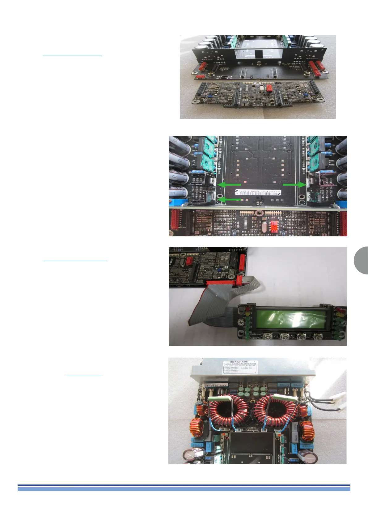
Install the three heat sink on the each voltage regulator
as showed in U1, U2 and U3 (Fig. 50)
(Fig. 49)
(Fig. 50)
(Fig. 51)
(Fig. 52)