42
K2 K3 | SERVICE MANUAL
INDEX
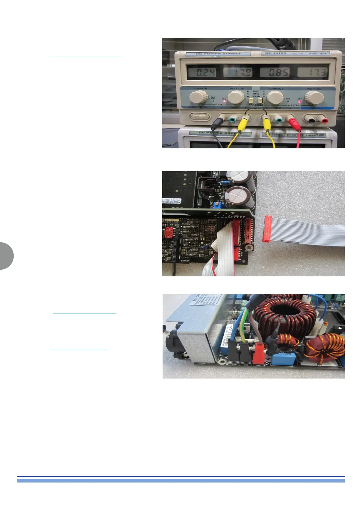
On the dual voltage power supply set the output voltage
at ±18 V
DC
Connect the K AMP VOLTAGE AUX CABLE ribbon cable
(20 pins) between CN14 of output stage board and the
power supply as portrayed in (Fig. 53, 54)
Warning: Power supply must be set to 0 Vdc and the voltage gradually increased to spec in order not
to damage the internal components
On the other dual voltage power supply sets the output
voltage at +0 V
DC
Connect the RAIL BUS AUX CABLE on the board
following polarity of the single wire:
Brown wire FA1 (+V
DC
)
Yellow wire FA3 (GND)
Blue wire FA5 (-V
DC
)
Connect the RAIL BUS AUX CABLE to the dual power
supply unit as portrayed in (Fig 55)
(Fig. 53)
(Fig. 54)
(Fig. 55)