43
K2 K3 | SERVICE MANUAL
INDEX
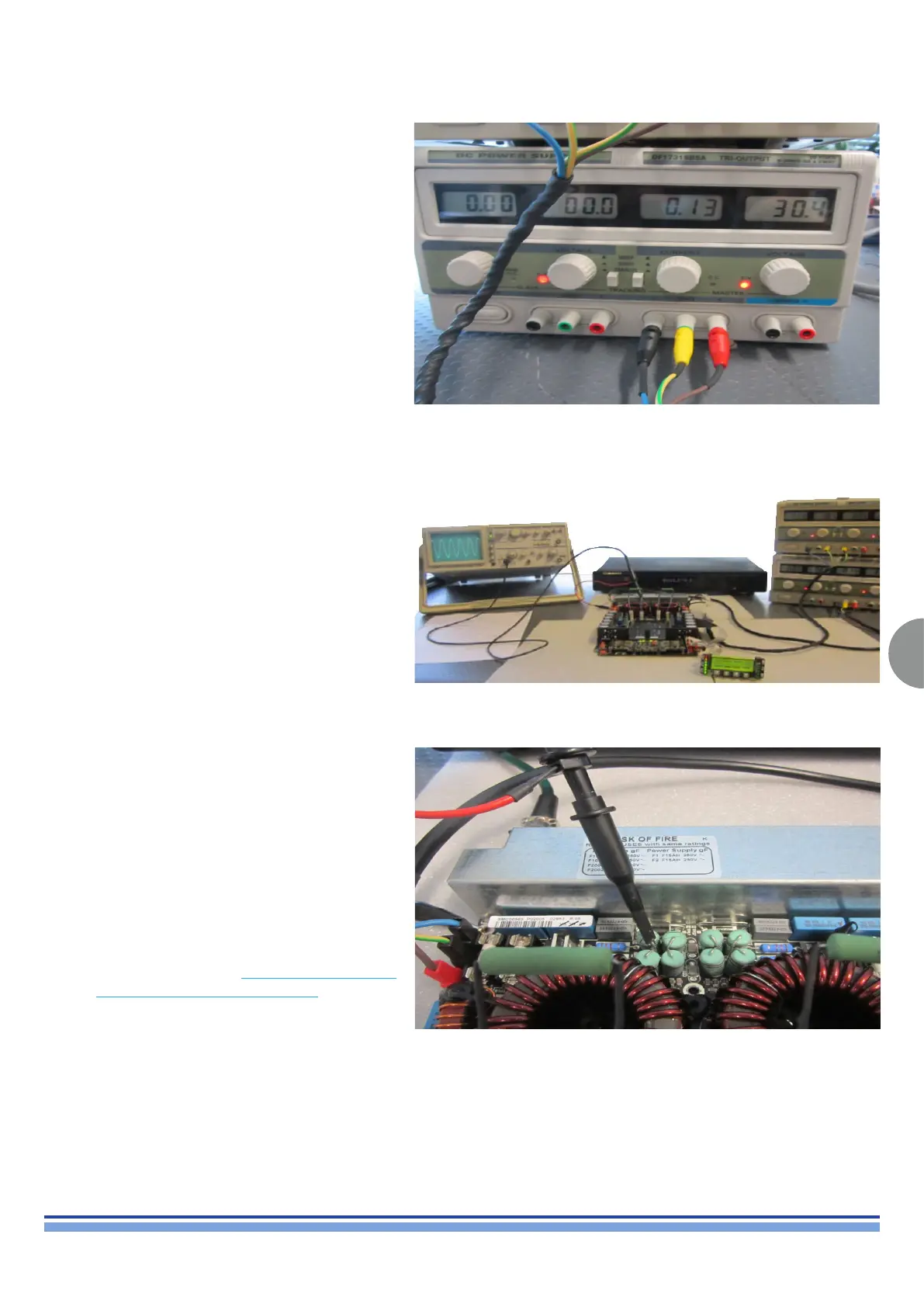
Consumption of the output stage board
Verify the consumption of the auxiliary voltage of the
output stage board (Fig. 56):
+18 V
DC
approx. 0,90 A (with rail bus voltage at 0 V
DC
)
-18 V
DC
approx. 0,25 A (with rail bus voltage at 0 V
DC
)
Increase the Rail Bus voltage gradually (we suggest 5 V
DC
per step) untill it reaches 30 V
DC
.
Verify that the consumption does not exceed 1A.
With Rail Bus voltage at 30 V
DC
, verify the consumption of
the auxiliary voltages: they should be as follow:
+18 V
DC
approx. 1,15 A
-18 V
DC
approx. 0,25 A
Connect signal generator or a CD player on the input of
CH1 and CH2 of output stage board and feed it with an
EIAJ test signal (Fig. 57).
Re-assemble the original boards
After these tests, remove the SERVICE CTRL BOARD
and the SERVICE FRONT DISPLAY BOARD with special
rmware vers. 2.0.5 and reinstall the original CTRL and D
FRONT DISPLAY boards.
Reinstall the latest Firmware version by means of the
rmware card
Output signal presence
(Fig. 56)
(Fig. 57)
(Fig. 58)
Verify the audio signal presence by means of an
oscilloscope on each and all four resistors assembled in
vertical position (Fig. 58):
R1044, R1045, R1046, R1073 (CH1)
R2044, R2045, R2046, R2073 (CH2)