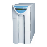
POWERVAR Security Plus UPS
34
Settings Pages
HIGH VOLTAGE LOW VOLTAGE
1) Inverter Off Setting 1) Inverter Off Setting
2) Audible Alarm Enable/Disable 2) Audible Alarm Enable/Disable
3) Frequency Window 3) Frequency Window
4) 240V Output Setting 4) 120V Output Setting
5) 230V Output Setting 5) 110V Output Setting
6) 220V Output Setting 6) 100V Output Setting
7) 208V Output Setting
8) 200V Output Setting
If the UPS enters a FAULT condition, it will switch to the fault display. All the fault condition displays are shown below:
1) Inverter fault
2) DC bus protection fault
3) Output short circuit fault
4) Overload protection fault (appears when UPS times out on overload and transfers to bypass)
5) Low battery voltage protection fault
6) Overload fault (appears when system is in inverter mode and detects an overload)
7) Over temperature protection fault
8) Fan fault
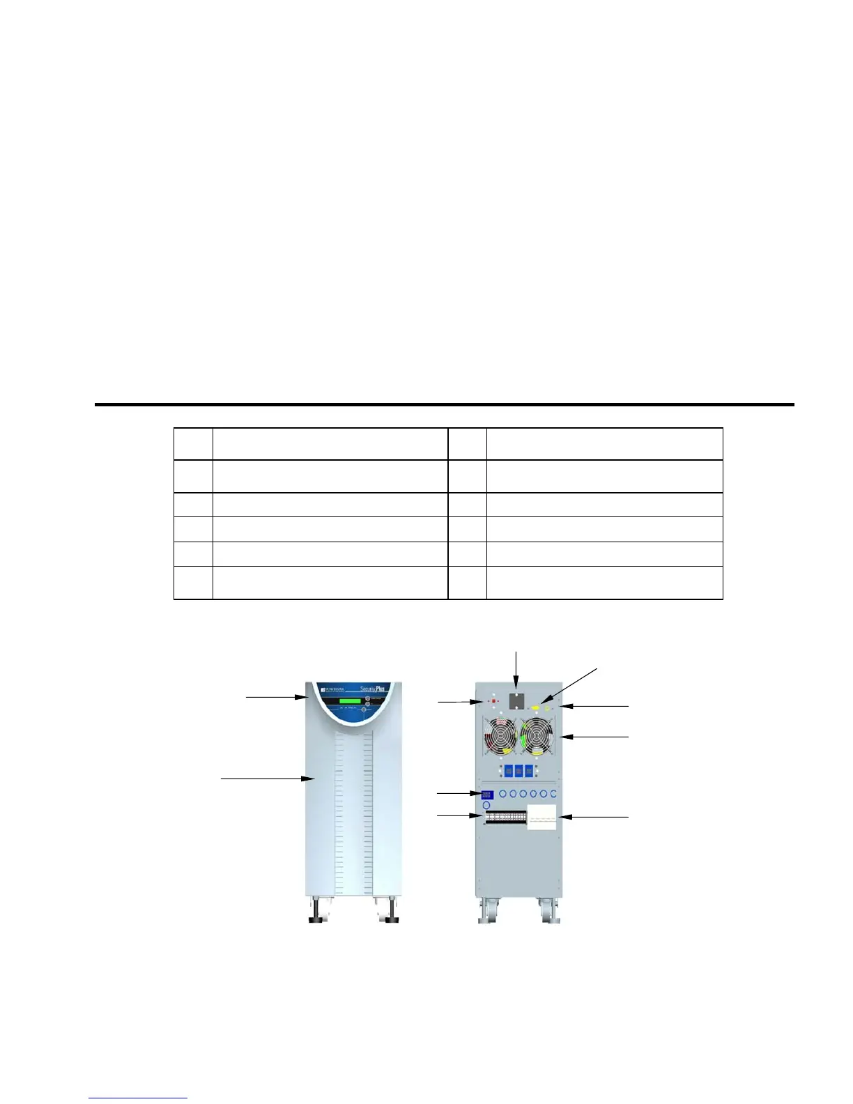
Item Description Item
Description
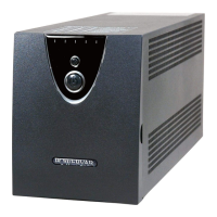
1 Operator Panel 6
Connection terminal block (not visible on
units equipped with receptacle panel)
2 Air inlet panels 7
RS232 Interface
3 Dial panel 8
USB Interface
4 Optional SNMP Interface 9
Hot swappable cooling fans
5 Connection point for rear receptacle panel
10
Main supply and battery switches (circuit
breakers)
Table 2-2
The front and rear panel layout of the Security Plus UPS is illustrated in Fig. 2-4 and Table 2-2.
1
2
6
5
4
3
10
9
8
7
Fi
ure 2-4