vii
Powerware 9315 (500 kVA--750 kVA) T1 and T3 Installation Addendum
164201244--001 REV. A 011500
Introduction
This manual provides information for removing and installi ng transformers T1 and T3.
The procedures in this manual are provided to facilitate shipping the system when
weight restrictions, at the receiving facility, prevent shipping the system with T1 and T3
assembled in the system cabinets.
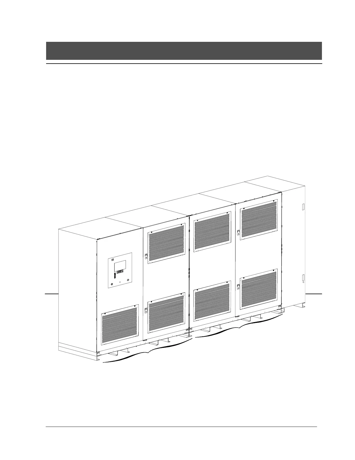
The UPS system is housed in a free-standing cabinet, divided into three sections to
facilitate shipping. The cabinet sections line up and match in style and color, and have
safety shields behind the doors for hazardous voltage protection. The following
illustration depicts a typical Powerware 9315 (500 kVA---750 kVA) UPS System.
MODULE
BYPASS
CABINET
OUTPUT
INVERTER
CABINET
INPUT
RECTIFIER
CABINET
Typical Powerware 9315 ( 500 kVA---750 kVA) UPS System