3-- 10
Powerware 9315 (500 kVA--750 kVA) T1 and T3 Installation Addendum
164201244--001 REV. A 011500
3.1.4 Assembly and Hardware Reinstallation
To reinstall assemblies and hardware removed in paragraph 3.1.1, perform the
following procedure:
NOTE: In the following steps, use the hardware removed in paragraph 3.1.1.
1. Install CPT4 panel into cabinet as follows (see figure 3---5):
a. Slide CPT4 panel over three screws in cabinet base.
b. Secure bottom o f CPT4 panel with three screws.
c. Secure top of CPT4 panel with three screws.
d. Connect connector P4 to J4.
2. Install lower deadfront panel and secure with four screws (see figure 3---5).
3. Install Input Filter A2 panel into cabinet as foll ows (see figure 3---5):
a. Slide Input Filter A2 panel lower mounting screws over slots in lower
deadfront panel.
b. Secure top of Input Filter A2 panel with three screws.
c. Secure three bottom screws attaching Input Filter A2 panel to lower
deadfront panel.
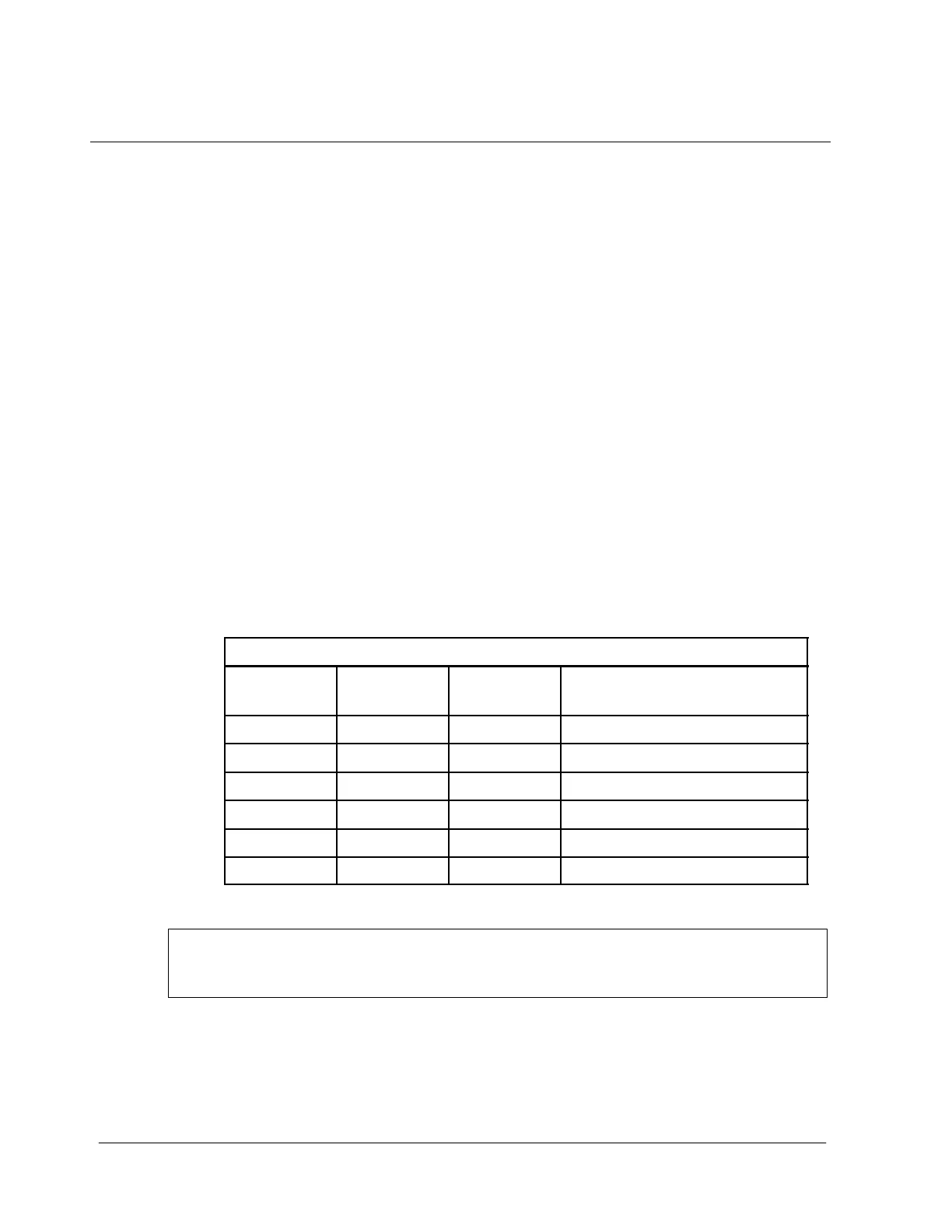
d. Connect wires to K 6 terminals using the information contained in
t a b l e 3 --- 2 .
Ta b l e 3 --- 2 . K 6 W i r e I n s t a l l a t i o n
Wire
Number
Number of
Wires
To Notes
109 1 2T1 Used with 50 Hz units only
110 1 4T2 Used with 50 Hz units only
111 1 6T3 Used with 50 Hz units only
109A 1 2T1
110A 1 4T2
111A 1 6T3
e. Connect connector A2P1 to A2J1.
WARNING:
Blower assembly B1--B4 are heavy and may require two persons to remove.
4. Position Blower Assembly B1---B4 onto cabinet base and slide forward (toward
the lower dead front panel) to engage screws in cabinet base (see figure 3---4).
5. Secure blower assembly to base with five front screws.
6. Secure three rear screws attaching blower assembly to base.