Chapter 4 Installation and commissioning
18
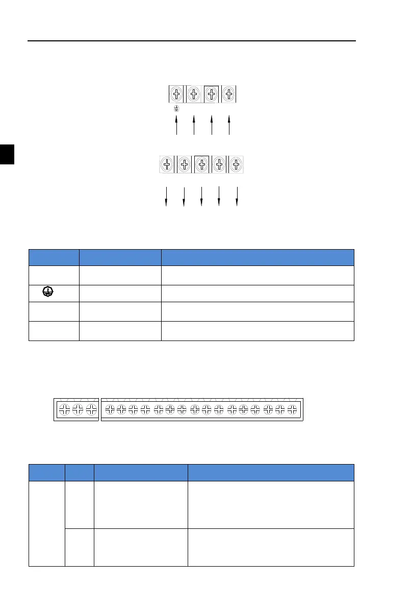
4-4.Main circuit terminal
4-4-1.Main circuit terminal arrange
R
S
T
Main power input
Ground terminal
U
V
W
Inverter output
Brake resistance
connecting terminal
P
RB
Figure 4-2.Main circuit terminal diagram
4-4-2.Function description of terminals
Connection point of AC input power supply, single-
phase connects to S, T
Braking resistor
terminals
Connect to braking resistor
Inverter output
terminals
Connect to three-phase motor
4-5.Control circuit terminals
4-5-1.Description of control circuit terminals
1. PI160MCB control circuit terminal
TA
TC TB
DI1
DI2
DI3
DI4
DI5
DI7
SPA
COM
PLC
24V
COM
10V
AI1
GND DA1
DI6
Figure 4-3.PI160 control circuit terminal
4-5-2.Control circuit terminal instruction
Output +10V power supply, maximum output
current:10mA
Generally it is used as power supply of
external potentiometer, potentiometer
resistance range:1kΩ to 5kΩ.
External+24V power
supply
Output +24V power supply, generally it is used
as power supply of digital input and output
terminals and external sensor.
Maximum output current: 200mA
 Loading...

