Chapter 4 Installation and commissioning
19
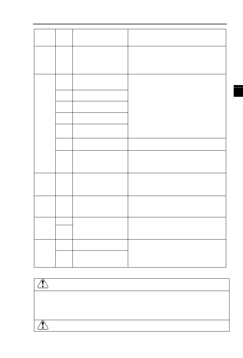
External power input
terminal
When external signal is used to drive, please
unplug JP1 jumpers,PLC must be connected to
external power supply, and to +24V (default) .
1.Input range: (DC 0V to 10V/0 to 20mA),
depends on the selected JP3 jumper on control
panel.
2.Input impedance: 20kΩ with voltage input,
500Ω with current input.
Multi function digital
input terminal 1
1. Opto-coupler isolation, compatible with
bipolar input
2. Input impedance: 3.3kΩ
3. Voltage range of level input : 24V±20%,
4, DI1-DI7 drive type by JP2 control, when
using external power source, please push off
JP2 jumper on the control panel.
Multi function digital
input terminal 2
Multi function digital
input terminal 3
Multi function digital
input terminal 4
Multi function digital
input terminal 6
Multi-function digital
input terminals
High-speed pulse input
terminals
In addition to DI1 ~ DI4, DI6 terminal
function, also can be used as high-speed pulse
input channel. Maximum input frequency of
100 KHZ.
The selected JP4 jumper on control panel
determines voltage or current output. Output
voltage range: 0V to 10V, output current range:
0mA to 20mA.
Optical coupling isolation, bipolar output open
collector output voltage range: 0 v ~ 24 v
output current range: 0 ma ~ 50 ma.
Relay output, TA normally open, TB normally
closed, TC common terminal, output function
is determined by F2.03 setting. Contact
capacity: 7A/AC250V
485 differential signal +
485 communication interface port, 485
differential signal port, 485 communication
interface standard use twisted pair or shielded
wire. JP1 jumper to decide whether to connect
terminal resistance.
485 differential signal -
4-6.Wiring precautions:
Make
sur
e that the power switch is in the OFF state before wiring operation, or electrical
shock may occu
r!
Wiring must be performed by a professional trained personnel, or this may cause damage to
the
equipment
and personal injury!
Must be
grounded
firmly, otherwise there is a danger of electric shock or fire hazard !
 Loading...

