Chapter 5 Function parameter
75
but do not excessively increases, or the lag effect will cause shock.
Vector control overexcitation gain
In the process of the inverter's deceleration, the over-excitation control can suppress the
increase of bus voltage to avoid overvoltage fault. The greater overexcitation, the stronger the
inhibitory effect.
For the occasions that the inverter's deceleration easily cause over pressure alarm , the
overexcitation gain needs to be improved. But if overexcitation gain is too large, which easily
lead to the increase of output current, you need to weigh in practical applications.
For the small inertia occasions that the inverter's deceleration will not cause voltage rise, it
is recommended to set overexcitation gain as 0; the set value is also suitable for the occasions
with braking resistor.
Excitation regulator proportional gain
Excitation regulator integral gain
Torque regulator proportional gain
Torque regulator integral gain
The regulator parameters of vector control current loop PI, the parameter will be obtained
automatically after performing asynchronous motor parameters comprehensive auto tunning
and generally do not need to modify it.
Note:the dimension that this current loop integral gain adopted is not the integration time,
but the direct set integral gain. Therefore, if the setting of current loop PI gain is too large,
which may cause the oscillation of entire control loop, in the event of oscillation, you can
manually reduce PI proportional gain and integral gain.
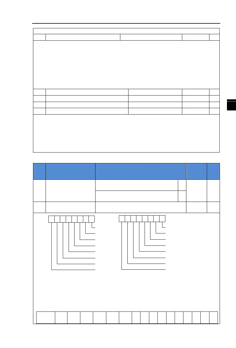
5-2-8.F6 group Keyboard and display
STOP/RESET key is enabled only in
keyboard operation mode
STOP/RESET key is enabled under any
operation mode
Running status display
paramters 1
0
1
2
3
4
5
6
7
8
910
11
121314
15
DI Input status
Output torque
Output power
Output current
(Hz)
Bus voltage
(V)
Set frequency
Running frequency
Output voltage
DO Output
AI1 Voltage
(Hz)
Count
Reserve
Length
Load speed
PID Setting
(A)
(kW)
(%)
(V)
(V)
Reserve
Figure 5-14:Running status display parameters 1
If the above parameters need to be displayed in operation, firstly set its position to 1, and
then set at F6.01 after converting the binary number to the hexadecimal number
e.g.:
Select monitor loading speed, set F6.01 No 14=1; Select monitor AI1 voltage, set F6.01 No
9=1. The rest be deduced by analogy. Hypothesis according to the requirement to all relative
position is set to 1 after get the following data:
 Loading...

