77
D
A
RE 1
RE 2
24
23
22
21
12
11
32
31
DP 1
PR 5111
.
5
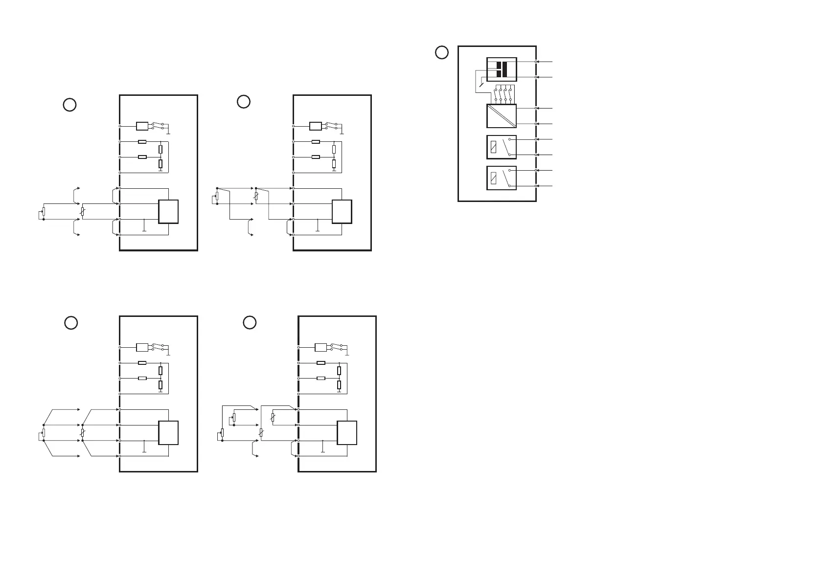
Alimentation
Sortie analogique -
Sortie analogique +
Relais 1
Relais 1
Relais 2
Relais 2
Alimentation
24...230 Vca /
24...250 Vcc
Câblage de la tension d’alimentation,
de la sortie analogique et des relais
de sortie.
76
SCHÉMAS DE RACCORDEMENTS
ENTRÉES RTD, SONDES RÉSISTIVES
(PT100, NI100...) ET RÉSISTANCES
MUX
10
50 k
PTC
5 M
41
42
43
44
51
52
53
54
DP2,1
DP2,2
Ω
Ω
Ω
Vreg
PR 5111
1
Potentiomètre
RTD
MUX
10
50 k
PTC
5 M
41
42
43
44
51
52
53
54
DP2,1
DP2,2
Ω
Ω
Ω
Vreg
PR 5111
.
2
Potentiomètre RTD
Entrée 2-fils RTD, sondes résistives et
résistances variables (potentiomètre).
Entrée 3-fils RTD, sondes résistives et
résistances variables (potentiomètre).
MUX
10
50 k
PTC
5 M
41
42
43
44
51
52
53
54
DP2,1
DP2,2
Ω
Ω
Ω
Vreg
PR 5111
3
Potentiomètre
RTD
MUX
10
50 k
PTC
5 M
41
42
43
44
51
52
53
54
DP2,1
DP2,2
Ω
Ω
Ω
Vreg
PR 5111
4
Chaud
Froid
Haut
Bas
Entrée 4-fils RTD, sondes résistives et
résistances variables (potentiomètre).
Entrée différentielle RTD, sondes
résistives et résistaces variables
(potentiomètre).