page 15
13. Secure the upright support to the base assembly. Refer to Diagram 7, #2 on
page 14. Align the mounting holes and thread the two bolts (F) with washers
(G) through opposite sides of the upright support and into the base assembly.
Finger tighten each bolt. Do not fully tighten the fasteners until the entire unit
has been assembled.
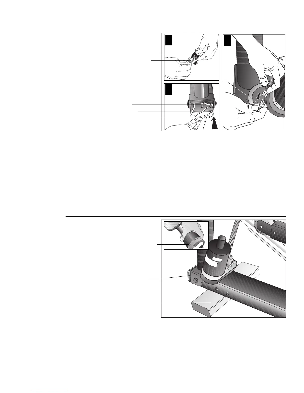
14. Connect the RJ45 cable into its black receptacle. Diagram 8, #1. Just like a
telephone connection, a definite “click” is heard when a good connection is
made. If you do not hear a “click,” try reinserting the cable connection again.
15. Connect the lift motor cable. Diagram 8, #2
16. Push excess cable inside base tube. Diagram 8, #3. Carefully, push any excess
cable behind the height adjustor threads that protrude from inside the base tube.
Diagram 8
Connect the
cables.
Cable connector
Cable receptacle
Place excess cable
into the base
assembly.
Height adjustor
threads
Base tube
Lift cable connector
2
1
3
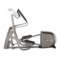
Diagram 9
Place the base
on supportive
blocks.
Adjustable rear pad
Supportive block
Base assembly
17. Rotate the rear pads. Diagram 9, inset. Ask your assistant to stabilize the unit
while you rotate the rear adjustable feet to the highest position. This procedure
lifts the base assembly off the floor which provides better access to the fasteners.
18. Place the base assembly on blocks. Diagram 9. Have an assistant lift the
upright support so that you can slide a block (packing material) under the front
of the unit.