page 14
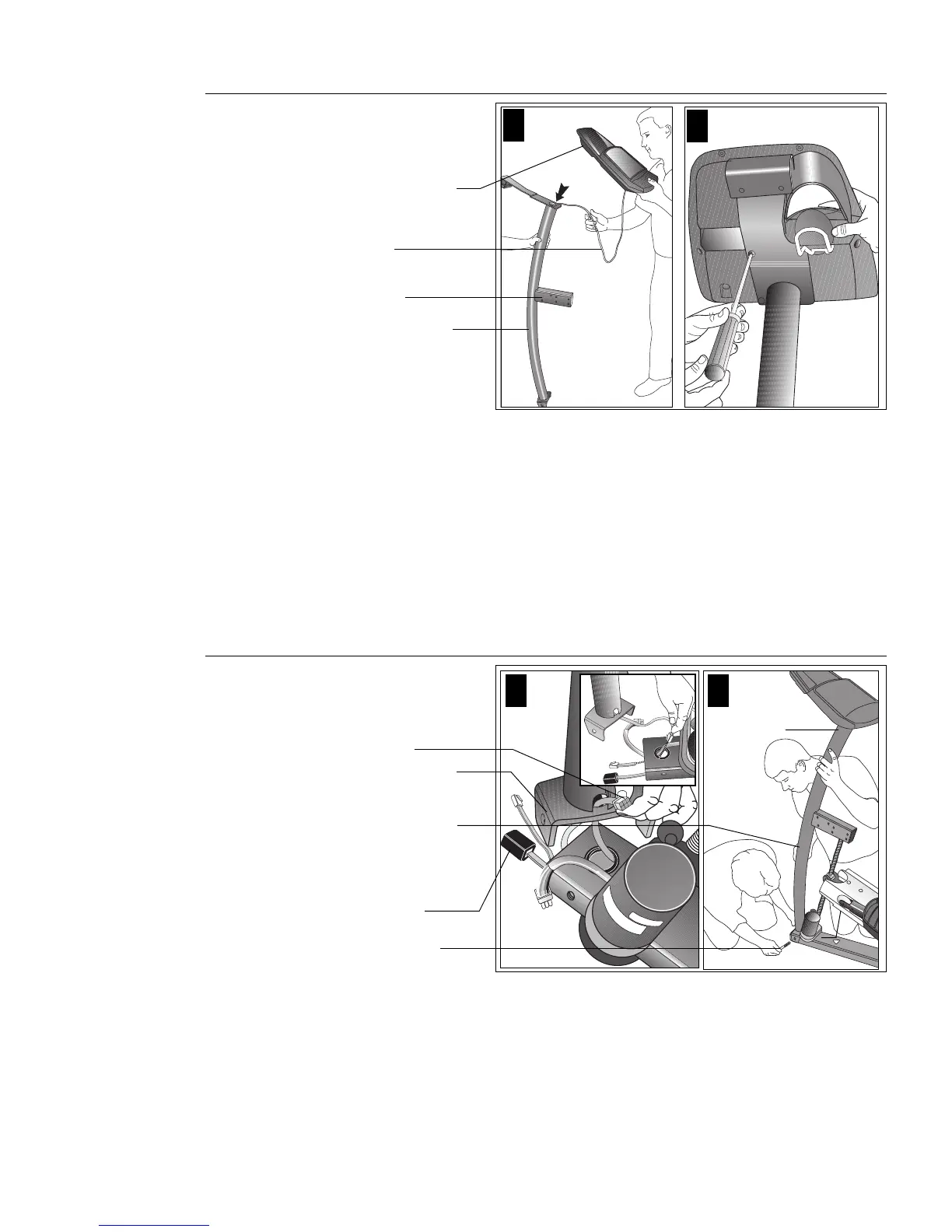
Diagram 6
8. Prepare for the attachment of the upright support to the base assembly.
Remove the four phillips-head screws (D), two bolts (F), and two washers (G) from
the Hardware kit. Place one washer (G) on each of the two bolts (F). Keep the
fasteners together. Refer to Diagrams 6 and 7.
9. Route the display console cable through the upright support. Diagram 6, #1.
Remove any tape or wire ties on the cable. Have an assistant hold the upright
support securely while you grasp the display console in one hand and route the
cable through the upright support with the other.
10. Attach the display console. Diagram 6, #2. Use the four phillips-head screws (D)
to attach the display console to the upright support. Have your assistant hold the
upright support securely while you align the mounting holes and tighten the screws.
11. Position the upright support over the base. Diagram 7. Have your assistant
move the upright support close to the front of the base assembly while you
thread the RJ45 cable through the grommet hole and out the front of the base
tube (refer to the inset in diagram 7, #1). Make sure that the display console (on
the upright support) faces the rear of the unit (refer to diagram 7, #2).
12. Route the lift motor cable through the cutout in the upright support.
Diagram 7, #1. While your assistant holds the upright support, thread the lift
motor cable through the cutout. Once the cable is routed, rest the upright
support on the base tube.
Route the cable and
attach the display
console to the
upright support.
Display console
CAUTION: Do not stretch, crimp, or
damage the cable. Excess cable may be
gently pushed into the base assembly.
Cables damaged by improper installation
will not be covered by the Precor limited
warranty.
CAUTION: As you assemble the unit, do
not fully tighten the fasteners until
instructed to do so. Finger tighten the
fasteners or use the hex key so that the
unit is stable, but the fasteners still allow
room for adjustments.
Upright support
Cable
Diagram 7
Route cable through
the upright support
and attach the upright
support to the base.
Upright support
Have your assistant
hold the upright
support while you
secure it to the base.
21
Two bolts (F)
with washers (G)
2
1
Lift cable
Upright
support
Upright support
bracket
RJ45 cable
receptacle