83
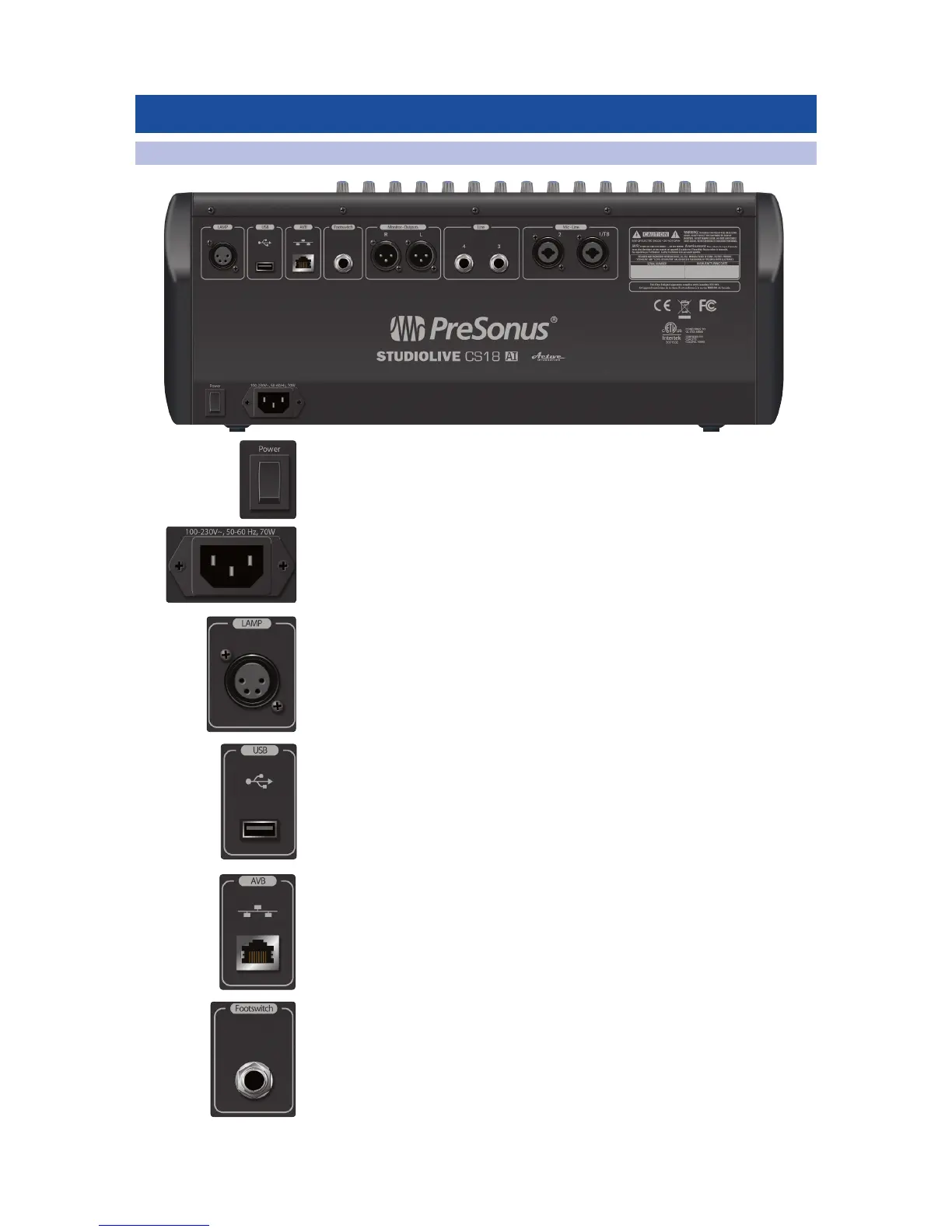
6 Rear Panel
6.1 Physical Connections and Controls
1. Power Switch.
2. Power Inlet. A standard IEC AC power inlet.
3. Lamp Jack. The 4-pin XLR lamp jack provides 12 volts to support
high-intensity lamps.
4. USB Port. The USB Type-A port is used for firmware updates using a thumb drive
and for Wi-Fi connections using the included USB Wi-Fi LAN adapter.
5. Ethernet AVB Jack. This RJ-45 jack supports Ethernet AVB networking, with
integrated connection and activity indicators. It provides the primary control
and audio transport. When connected on an AVB-compliant network or to an
AVB-compliant device, the built-in 4x2 audio is available on the network.
When connected to a non-AVB-compliant network or device, only control
data is available.
6. Footswitch Input. A ¼-inch jack supports a momentary footswitch. The target
for footswitch control is set in the Master Control touchscreen.