EasyManua.ls Logo

Princeton Instruments PI-MAX 3 System - User Manual

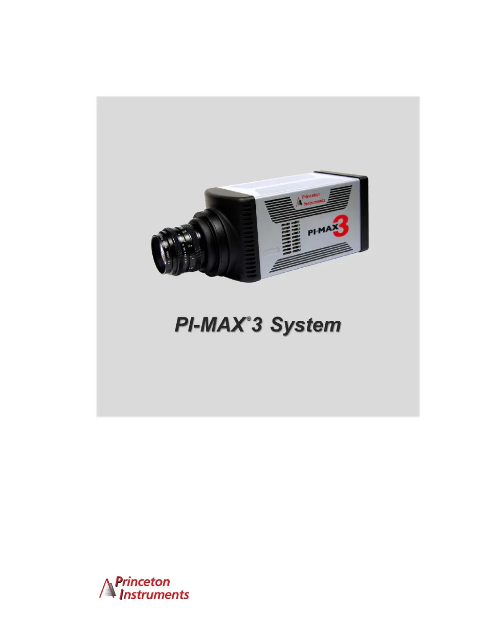
Princeton Instruments PI-MAX 3 System
150 pages
Print Icon
To Next Page IconTo Next Page
Loading...
4411-0129
Version 1.A
September 8, 2010
*4411-0069*

Table of Contents

Questions and Answers

  • S
    Shirley BurnsAug 2, 2025
    Why is my Princeton Instruments Security Camera not responding?
    • K
      kimberlysmithAug 2, 2025
      If your Princeton Instruments Security Camera isn't responding, start by ensuring the controller is turned on and that the interface card, its driver, and the interface cable are correctly installed. If the camera is on, the issue might stem from the interface card, driver conflicts, or cable connections. If the interface card wasn't installed initially, turn off the PI-MAX3 power, install the card following the manufacturer's instructions, connect it to the GIG-E port, and perform a custom WinSpec/32 or WinView/32 installation, selecting the appropriate interface component. Also, if the interface card is already installed, verify all cable connections are secure.
  • T
    timothymasseyAug 8, 2025
    What to do if Princeton Instruments PI-MAX 3 System stops working?
    • S
      Stephanie SmithAug 9, 2025
      If your Princeton Instruments Security Camera stops working, begin by turning off all AC power. Then, check all cables to ensure they are securely fastened and that all locking screws and slide latches are correctly in place. After addressing any identified issues, turn the system back on. If the problem persists, further assistance is needed.
  • R
    Richard HubbardAug 20, 2025
    What to do if Princeton Instruments Security Camera alarm sounds repetitively?
    • M
      Michele HallAug 20, 2025
      If the alarm on your Princeton Instruments Security Camera sounds repetitively, immediately reduce the light entering the camera. You can do this by switching the I.I.T. switch on the back of the PI-MAX3 to "OFF" until you lower the source illumination, by decreasing the lens aperture, or by completely blocking the light into the camera window with a lens cap or equivalent until the light level has been lowered. If the alarm continues even with low illumination, switch the I.I.T. to "OFF", turn off the PI-MAX3 power supply, and contact the factory, as this may indicate intensifier damage or another issue needing immediate attention.
  • D
    Denise AndersonAug 27, 2025
    Why does baseline signal suddenly change on Princeton Instruments PI-MAX 3 System?
    • G
      gregoryperezAug 27, 2025
      If the baseline signal on your Princeton Instruments Security Camera suddenly changes by more than 1000 ADU, it could be due to a change in the temperature setting, which is normal. However, if the temperature setting hasn't been changed, it may indicate excessive humidity in the CCD enclosure. In this case, turn off the system immediately and have it serviced by Princeton Instruments or an authorized service facility to prevent permanent damage.
  • K
    Kathy ButlerNov 14, 2025
    How to fix temperature lock issues on Princeton Instruments Security Camera?
    • B
      Brooke GomezNov 14, 2025
      If the temperature lock cannot be achieved or maintained on your Princeton Instruments Security Camera, several factors could be the cause. If the ambient temperature is greater than +20°C, especially with TE-cooled cameras, cool the camera environment or raise the set temperature. Ensure there's adequate airflow around the camera, with at least two inches of clearance around the vented covers, and that any enclosure has unrestricted airflow. Check for kinked hoses and unkink them. Also, verify the coolant level and add a 50:50 mix of ethylene glycol and water if it's low, following the manufacturer’s instructions. Remove any air from the hoses and add coolant as needed. If the circulator pump isn't working, turn it off and contact the manufacturer's Customer Support. For CoolCUBEII system...

Summary

Chapter 1 Introduction

PI-MAX3 System Components

Details the standard hardware and software components of a PI-MAX3 system.

Camera Head

Describes the PI-MAX3 camera head, including CCD, intensifier, and cooling.

Summary of PI-MAX3 Data Acquisition

Explains the process of acquiring data with the PI-MAX3 camera.

Safety Information

Provides essential safety guidelines and warnings for operating the PI-MAX3.

Precautions

Lists important safety measures to prevent system damage.

Cleaning and Maintenance

Instructions for cleaning the camera and its optical surfaces.

Manual Organization

An overview of the manual's structure and chapter contents.

Chapter 2 Installation Overview

System Requirements

Details environmental, ventilation, power, and host computer requirements.

Software Installation

Steps for installing the WinView/32 or WinSpec/32 application.

Making the Camera-Circulator Connections

Procedure for connecting the liquid-cooled system.

Entering the Default Camera System Parameters into WinX

Configuring initial system parameters using the Camera Detection wizard.

Chapter 3 System Setup

Dangers and Warnings

Highlights critical hazards and precautions during system setup.

Unpacking the System

Instructions for unpacking and inspecting system components.

Host Computer

Specifies the minimum requirements for the host computer system.

Mounting the PI-MAX3

Guidance on physically mounting the PI-MAX3 camera.

Chapter 4 First Light

Required Equipment and Cables

Lists all necessary hardware and cables for initial operation.

Cable Connections

Details the cabling configuration for basic system setup.

Turning on the System and Setting Up the Software

Steps for powering on the system and launching the control software.

Configuring the Software

Steps to configure the software for initial operation.

Initial Data Acquisition

Procedure for acquiring the first image or spectrum.

Focusing

Instructions for adjusting the lens focus for optimal image clarity.

Chapter 5 General Operation Factors

Data Acquisition Sequence

Explains the step-by-step process of data acquisition.

Pre-Exposure Removal of Accumulated Charge

Methods to minimize dark charge accumulation before exposure.

Temperature Control

Details on setting and maintaining the camera's operating temperature.

Background Subtraction

Techniques for removing background noise from acquired data.

Readout of the Array

Describes how charge is transferred and read from the CCD array.

Binned Readout (Hardware Binning)

Explanation of hardware binning for faster readout and improved S/N.

Software Binning

Post-acquisition processing for improving S/N ratio.

Chapter 6 Gated Operation

Introduction

Overview of gated operation for detecting low light signals.

Precautionary Measures

Safety considerations specific to gated operation.

MCP Bracket Pulsing

Technique to enhance the intensifier's on/off ratio in UV.

Limitations of Bracket Pulse Gating

Discusses constraints and limitations of MCP bracket pulsing.

Single Shot

Procedure for capturing single, non-repeatable events.

Chapter 7 Timing Generator Pulses and Sequences

Pulse Set

Describes the signals that constitute a timing pulse set.

Supported Timing Generator Trigger Modes

Explains the different trigger modes for timing generation.

Single Sequence

Details on repeating a pulse set multiple times.

Chapter 8 Dual Image Feature (DIF)

Introduction

Explains the purpose of the Dual Image Feature (DIF).

Requirements

Lists the prerequisites for enabling DIF operation.

Interline CCD Operation

Describes how interline CCDs facilitate rapid image acquisition.

Timing Modes

Details the timing modes available for DIF operation.

Single Trigger Mode

Configuration for DIF with a single trigger event.

Dual Trigger Mode

Configuration for DIF with two separate trigger events.

Chapter 9 Tips and Tricks

Overexposure Protection

Measures to prevent detector damage from excessive light.

Signal Delay

Ensuring proper timing for signal detection.

Time Budgets

Analysis of system delays for timing coincidence.

Adjusting the Signal Delay

Fine-tuning delays to achieve signal coincidence.

Lasers

Considerations for using lasers with the PI-MAX3 system.

Lens Performance

How lens characteristics impact system performance.

Temperature Lock

Ensuring stable and optimal camera operating temperature.

Chapter 10 System Component Descriptions

PI-MAX3 Camera

Detailed description of the PI-MAX3 camera unit.

Mount Adapters

Information on C-mount, F-mount, and spectroscopy mounts.

Switches, Connectors and Indicators

Description of physical interface ports and controls.

Coolant ports

Details on the ports for liquid cooling connections.

AUX I;O

Overview of auxiliary input/output signals and their functions.

Application Software

Description of WinView/32, WinSpec/32, and Monarch software.

Chapter 11 Troubleshooting

Camera Is Not Responding

Steps to diagnose and resolve communication issues with the camera.

Cooling Troubleshooting

Guidance for resolving problems with temperature control.

Ethernet Network is not accessible

Steps to troubleshoot network connectivity issues.

Excessive Readout Noise

Diagnosing and resolving issues related to excessive noise.

Appendix A Specifications

PI-MAX3

Technical specifications for the PI-MAX3 camera system.

Gating

Specifications related to the intensifier gating capabilities.

Intensifier Quantum Efficiency

Quantum efficiency curves for different intensifier types.

Appendix B Outline Drawings

PI-MAX3

Mechanical outline drawing of the PI-MAX3 camera with C-mount adapter.

PI-MAX3 Power Supply

Outline drawing of the PI-MAX3 power supply unit.

CoolCUBEII Circulator

Outline drawing of the CoolCUBEII coolant circulator.

Appendix C Software

Camera State

Dialog box showing and allowing restoration of camera start-up state.

Main tab page (Experiment Setup on Acquisition menu)

Specifies essential parameters like Exposure Time and Gain.

Pulsers dialog box

Allows selection and setup of timing generators.

Appendix D Extender Bracket Kit

To secure the plate to the camera

Instructions for mounting the PI-MAX3 using the extender bracket.

Appendix E Mounting and Focusing C-Mount and F-Mount Lenses

Mounting the Lens

Procedure for attaching and detaching C-mount and F-mount lenses.

Mounting Orientation

Guidance on camera mounting positions and support requirements.

Focusing

Methods for achieving sharp focus with mounted lenses.

Appendix F C-, F-, and Spectroscopy-Mount Adapters

To change from one adapter to another

Steps for swapping different types of lens/spectrograph adapters.

Appendix G Spectrograph Adapters

Introduction

Overview of PI-MAX3 spectrograph adapter options.

Spectrograph-Detector Focusing

Procedure for aligning the detector with the spectrograph focal plane.

Acton (Sliding Tube)

Assembly instructions for the Acton Sliding Tube adapter.

Acton (C-Mount Adapter)

Assembly instructions for the Acton C-Mount Adapter.

Chromex 250 IS

Assembly instructions for the Chromex 250 IS spectrograph adapter.

Appendix H Glossary

Binning

Definition of combining pixels for faster readout or improved S/N.

Dark Charge or Dark Current

Explanation of thermally induced charge accumulation in the CCD.

Exposure Time

The duration for which the CCD array integrates incoming signal.

Gate Mode

Intensifier mode where photocathode is biased on during gate pulses.

Gate Width

The time duration during which light is detected by the intensifier.

Declaration of Conformity

Warranty & Service

Limited Warranty

Details the warranty terms and conditions for PI products.

Basic Limited One (1) Year Warranty

Covers defects in materials and workmanship for one year.

Software Limited Warranty

Warranty terms for manufactured software discs.

Your Responsibility

Outlines customer obligations for warranty service and claims.

Contact Information

Provides contact details for technical support and service.

Princeton Instruments PI-MAX 3 System Specifications

General IconGeneral
BrandPrinceton Instruments
ModelPI-MAX 3 System
CategorySecurity Camera
LanguageEnglish

Related product manuals