Chapter 6 Gated Operation 67
11. After verifying all connections and equipment readiness, click on Acquire to begin
acquiring the spectra (or images).
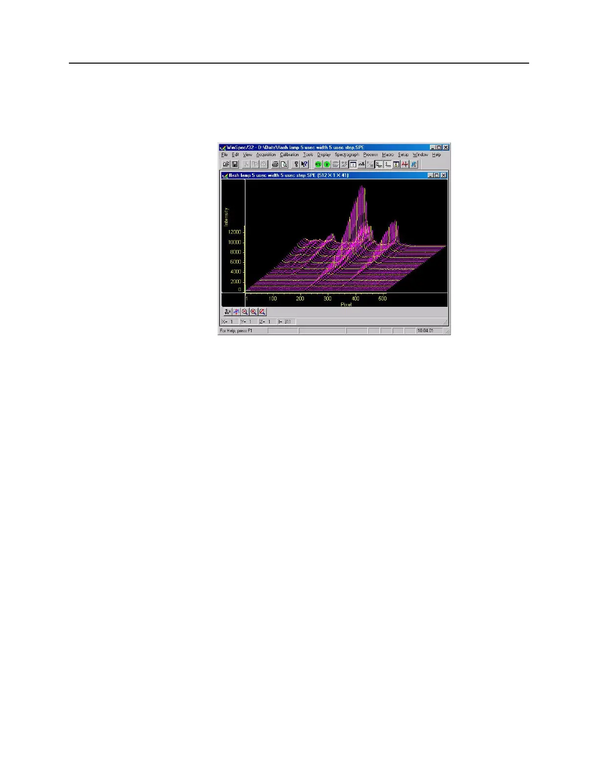
12. Figure 35 displays the 3-D graph for a “Sequential-Repetitive" experiment with Fixed
Width and Variable Delay (as set in Figure 31 and Figure 32).
Figure 35. Experiment Results in 3-D
PI-MAX3 as Master Clock
If you have a light source that has a "Trigger In", the PI-MAX3 SyncMASTER function
can be used as the Master clock (cable connections shown in Figure 36). The setup
procedure is much the same as that given for the "Experiment as Master Clock". The
differences are that a cable is connected between the PI-MAX3’s AUXI/O T0 BNC and
the light source (experiment) for triggering the event and that the 25 ns propagation delay
for the external trigger is no longer a factor.


 To Next Page