Chapter 6 Gated Operation 65
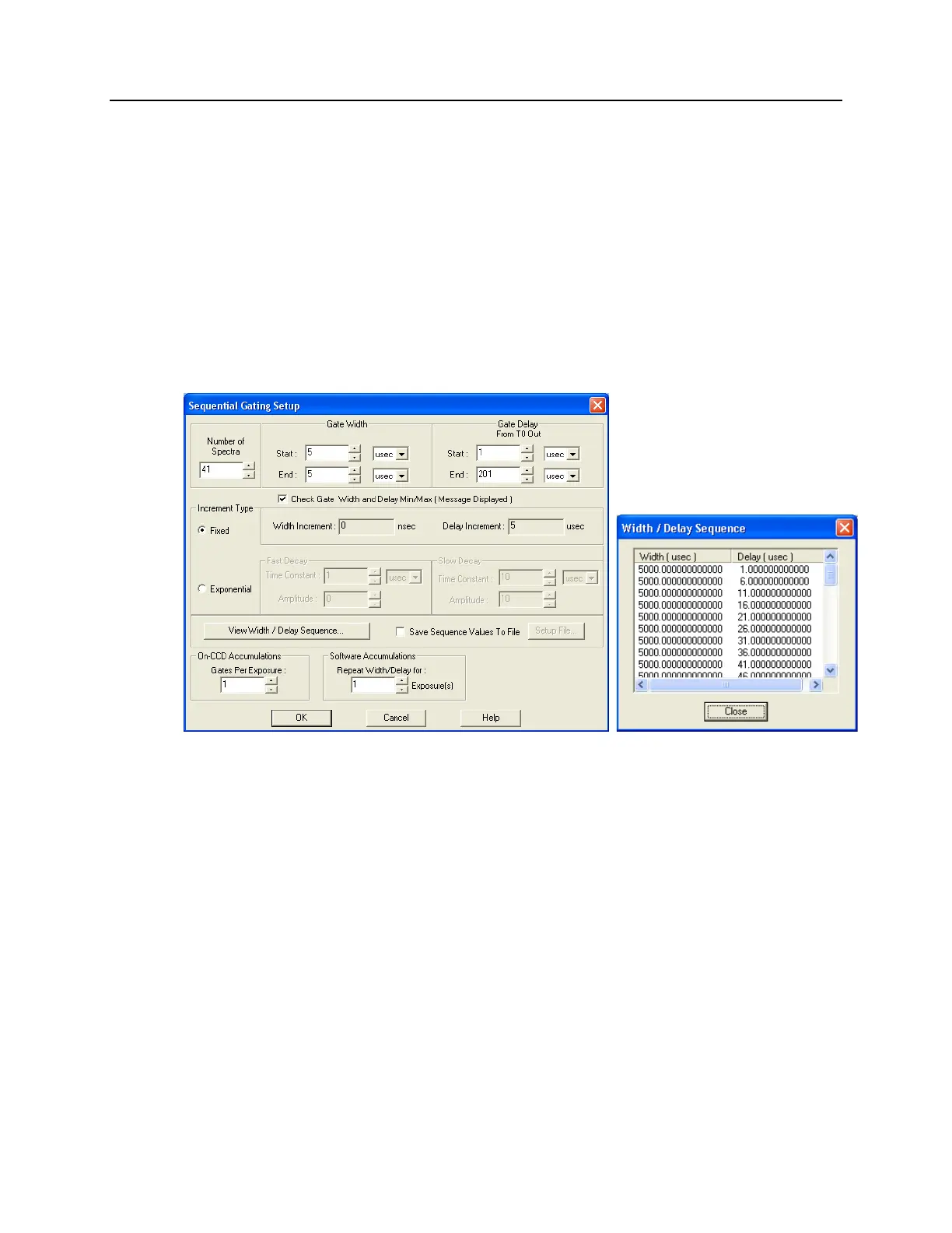
c. Click on "Setup…" and define the pulse sequence on the Sequential Gating Setup
dialog box. See Figure 32.
Enter the number of spectra to be acquired (in this case, 41).
Select "Fixed Increment".
Enter the start and end times for the gate width. (Since this experiment
requires a fixed gate width these values will be the same.)
Enter the start and end durations for the gate delay. (For this experiment, the
start delay is 1 µs and the end delay is 201 µs.)
Then select the number of gates per exposure (in this case, 1).
To check the gate delay for each of the 41 spectra, click on "View
Width/Delay Sequence."
Figure 32. Sequential Gating Setup and Width/Delay Sequence dialog boxes
d. The functions on the Trigger Out tab page allow you to enable the
SyncMASTER trigger output from the SyncMASTER1 and SyncMASTER2
connectors on the AUX I/O cable and set up the Aux. Out signal at the AUX
OUT connector on the rear of the PI-MAX3.
When you enable SyncMASTER 1, the output of the SyncMASTER1
connector will be at the frequency entered on the Trigger In tab page.
The output of the SyncMASTER2 connector will be at the same frequency
as that of SyncMASTER1. However, you can enter a delay so the edges of
that signal will occur after the edges of SyncMASTER1.
If you are using the Aux. Out signal from the SuperSYNCHRO to trigger a
piece of equipment, then enter the Auxiliary pulse delay time on the Trigger
Out tab page (Figure 33). The delay is based on T0 (in effect it is a delay
from SyncMASTER1which also starts at T0). Enter the pulse width needed
to trigger the equipment.

 Loading...
