TABLE OF CONTENTS
General instructions ............................................................................................................................. 2
Required equipment / tools / materials for installing a complete system ............................................. 3
Vehicle check ....................................................................................................................................... 3
Base diagram ....................................................................................................................................... 4
VSI approval numbers.......................................................................................................................... 5
Mounting and connection points .......................................................................................................... 6
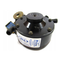
Mounting the reducer ........................................................................................................................... 7
Water connections ............................................................................................................................... 8
Overpressure connection ..................................................................................................................... 9
Mounting the inlet manifold couplings ................................................................................................ 10
Mounting the ValveCare manifold couplings ...................................................................................... 11
Mounting the VSI injector rail ............................................................................................................. 12
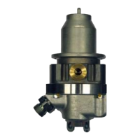
Mounting the Prins filter unit ............................................................................................................... 13
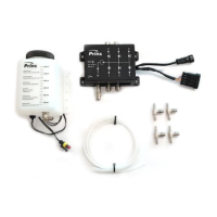
Mounting ValveCare 1 ........................................................................................................................ 14
Mounting ValveCare 2 ........................................................................................................................ 15
LPG hoses ......................................................................................................................................... 16
Mounting the VSI computer bracket ................................................................................................... 17
Mounting the fuel selection switch ..................................................................................................... 18
Electrical connections ........................................................................................................................ 19
Electrical connections ........................................................................................................................ 20
Insulate all not used wires. ................................................................................................................. 20
Electrical connections ........................................................................................................................ 21
Checklist after installation .................................................................................................................. 22
Trouble code chart ............................................................................................................................. 23
FOR EXPLANATION AND CIRCUIT DIAGRAMS SEE : INSTALLATION MANUAL GENERAL PART 1 / 2
EXPLANATION OF SYMBOLS :