3310F Series Operation Manual 5
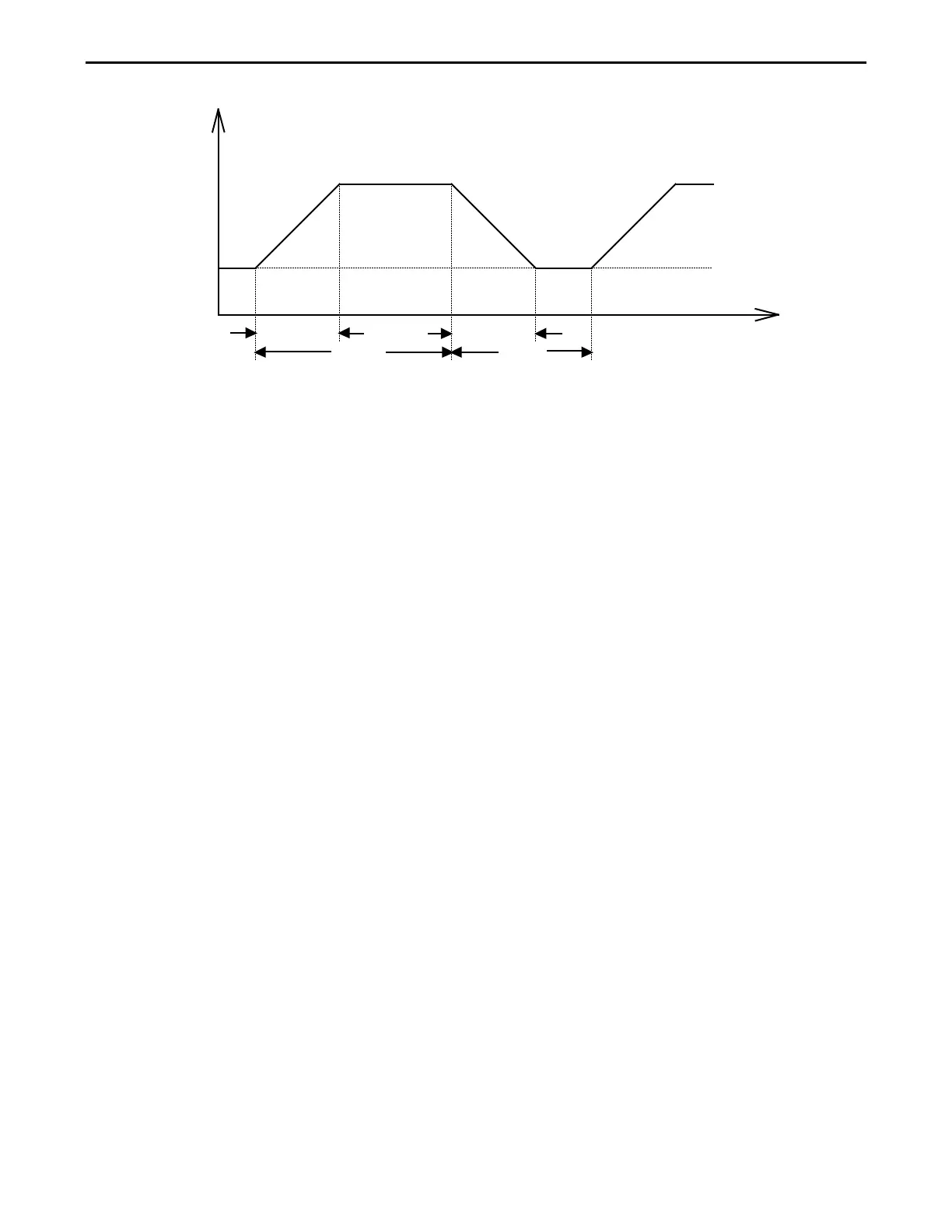
Fig 1-10 Dynamic Wave form
The dynamic waveform can also be set up via the optional computer interface. Dynamic
waveform settings made from the front panel of the load module can also be saved in the
memory of the mainframe. For the store/recall procedure and the computer command set
please refer to the relevant operating manual for the 3300F/3302F/3305F mainframes.
Further dynamic waveform definitions are:
• The period of dynamic waveform is Thigh + Tlow
• The dynamic frequency = 1 /( Thigh + Tlow )
• The duty cycle = Thigh / ( Thigh + Tlow )
The analogue programming input also provides a convenient method of implementing a
dynamic waveform. Please see the section 3.1.26 titled ‘Analog Programming Input’ for
further information.
1.1.6. Slew Rate
Slew rate is defined as the change in current or voltage over time. A programmable slew
rate allows for a controlled transition from one load setting to another. It can be used to
minimize induced voltage drops on inductive power wiring, or to control induced transients
on a test device (such as would occur during power supply transient response testing).
In cases where the transition from one setting to another is large, the actual transition time
can be calculated by dividing the voltage or current transition by the slew rate. The actual
transition time is defined as the time required for the input to change from 10% to 90% or
from 90% to 10% of the programmed excursion.
In cases where the transition from one setting to another is small, the small signal
bandwidth (of the load) limits the minimum transition time for all programmable slew rates.
Because of this limitation, the actual transition time is longer than the expected time based
on the slew rate, as shown in Figure 1-11
 Loading...