6 PRODIGIT
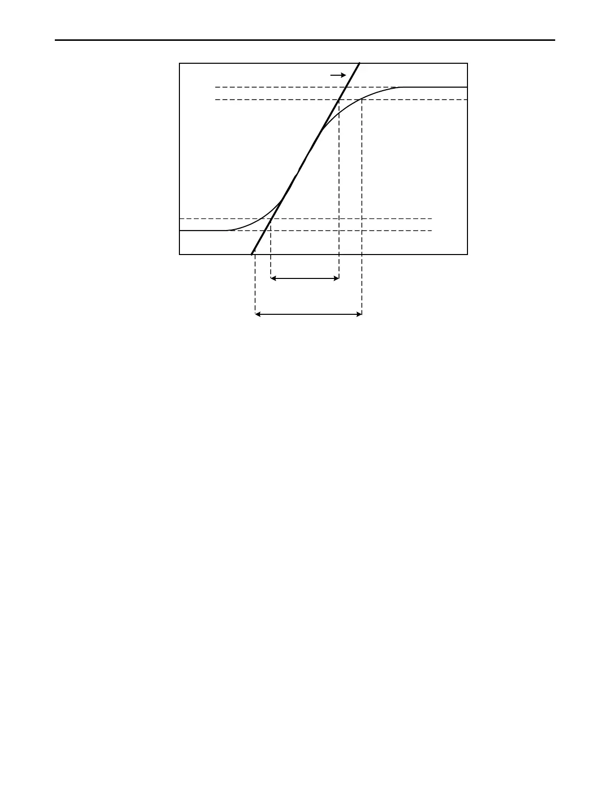
Slew Rate
Expected time
Actual Time
10 %
0 %
100 %
90 %
Voltage (Volts)
Or
Current (Amps)
Slew Rate
Time
mS
Fig 1-11 Rise Time Transition Limitation
Therefore, both minimum transition time and slew rate must be considered when
determining the actual transition time.
Following detail description is exclude in operation manual.
The minimum transition time for a given slew rate as about a 30% or greater load change,
The slew rate increases from the minimum transition time to the Maximum transition time
at a 100% load change. The actual transition time will be either the minimum transition time,
Or the total slew time (transition divided by slew rate), whichever is longer.
EX: 3311F 60V/60A/300W (CCH - CCL >60Ax 30%)
Use the following formula to calculate the minimum transition time for a given slew rate
Min transition time=18A/slew rate (in amps/second).
180uS (18A/0.1) x 0.8(10%~90%) =144uS
Use the following formula to calculate the maximum transition time for a given slew rate
Max transition time=60/slew rate (in amps/second).
600uS (60A/0.1) x 0.8(10~90%) = 480uS
EX. CCH=16A, CCL=0A Slew Rate =0.1A, the expected time is 128uS but the actual
Transition Time will be limited to 144uS
160uS (16/0.1) x 0.8(10%~90%) = 128uS
 Loading...